


3−32
X1
24.576 MHz
I
S
X1
C
PHY
+ C
BD
X0
C10
C9
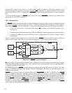
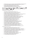
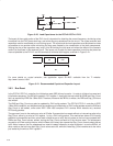
Figure 3−20. Load Capacitance for the PCI7x21/PCI7x11 PHY
The layout of the crystal portion of the PHY circuit is important for obtaining the correct frequency, minimizing noise
introduced into the PHY phase-lock loop, and minimizing any emissions from the circuit. The crystal and two load
capacitors must be considered as a unit during layout. The crystal and the load capacitors must be placed as close
as possible to one another while minimizing the loop area created by the combination of the three components.
Varying the size of the capacitors may help in this. Minimizing the loop area minimizes the effect of the resonant
current (Is) that flows in this resonant circuit. This layout unit (crystal and load capacitors) must then be placed as
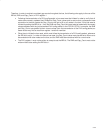
close as possible to the PHY X1 and X0 terminals to minimize etch lengths, as shown in Figure 3−21.
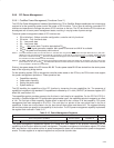
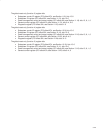
C9 C10
X1
For more details on crystal selection, see application report SLLA051 available from the TI website:
http://www.ti.com/sc/1394.
Figure 3−21. Recommended Crystal and Capacitor Layout
3.9.3 Bus Reset
In the PCI7x21/PCI7x11 controller, the initiate bus reset (IBR) bit may be set to 1 in order to initiate a bus reset and
initialization sequence. The IBR bit is located in PHY register 1, along with the root-holdoff bit (RHB) and Gap_Count
field, as required by IEEE Std 1394a-2000. Therefore, whenever the IBR bit is written, the RHB and Gap_Count are
also written.
The RHB and Gap_Count may also be updated by PHY-config packets. The PCI7x21/PCI7x11 controller is IEEE
1394a-2000 compliant, and therefore both the reception and transmission of PHY-config packets cause the RHB and
Gap_Count to be loaded, unlike older IEEE 1394-1995 compliant PHY devices which decode only received
PHY-config packets.
The gap-count is set to the maximum value of 63 after 2 consecutive bus resets without an intervening write to the
Gap_Count, either by a write to PHY register 1 or by a PHY-config packet. This mechanism allows a PHY-config
packet to be transmitted and then a bus reset initiated so as to verify that all nodes on the bus have updated their
RHBs and Gap_Count values, without having the Gap_Count set back to 63 by the bus reset. The subsequent
connection of a new node to the bus, which initiates a bus reset, then causes the Gap_Count of each node to be set
to 63. Note, however, that if a subsequent bus reset is instead initiated by a write to register 1 to set the IBR bit, all
other nodes on the bus have their Gap_Count values set to 63, while this node Gap_Count remains set to the value
just loaded by the write to PHY register 1.