


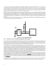

3−10
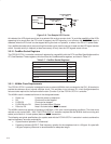
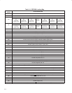
PCI7x21/
PCI7x11
Current Limiting
R ≈ 150 Ω
Socket A
LED
MFUNCx
Current Limiting
R ≈ 150 Ω
Socket B
LED
MFUNCy
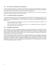
Figure 3−6. Two Sample LED Circuits
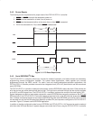
As indicated, the LED signals are driven for a period of 64 ms by a counter circuit. To avoid the possibility of the LEDs
appearing to be stuck when the PCI clock is stopped, the LED signaling is cut off when the SUSPEND
signal is
asserted, when the PCI clock is to be stopped during the clock run protocol, or when in the D2 or D1 power state.
If any additional socket activity occurs during this counter cycle, then the counter is reset and the LED signal remains
driven. If socket activity is frequent (at least once every 64 ms), then the LED signals remain driven.
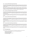
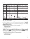
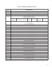
3.5.10 CardBus Socket Registers
The PCI7x21/PCI7x11 controller contains all registers for compatibility with the PCI Local Bus Specification and the
PC Card Standard. These registers, which exist as the CardBus socket registers, are listed in Table 3−7.
Table 3−7. CardBus Socket Registers
REGISTER NAME OFFSET
Socket event 00h
Socket mask 04h
Socket present state 08h
Socket force event 0Ch
Socket control 10h
Reserved 14h−1Ch
Socket power management 20h
3.5.11 48-MHz Clock Requirements
The PCI7x21/PCI7x11 controller is designed to use an external 48-MHz clock connected to the CLK_48 terminal to
provide the reference for an internal oscillator circuit. This oscillator in turn drives a PLL circuit that generates the
various clocks required for the flash media function (Function 3) of the PCI7x21/PCI7x11 controller.
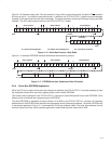
The 48-MHz clock is needed as follows in the designated states:
• Power−up Follow the power-up sequence
• D0: Clock must not be stopped
• D1/D2/D3: Clock can be stopped
• D1/D2/D3
hot
to D0: Need 10 clocks before D0 state
• D3
cold
to D0: Need 10 clocks before PRST de-assert
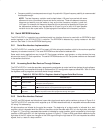
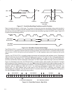
The 48-MHz clock must maintain a frequency of 48 MHz ± 0.8% over normal operating conditions. This clock must
maintain a duty cycle of 40% − 60%. The PCI7x21/PCI7x11 controller requires that the 48-MHz clock be running and
stable (a minimum of 10 clock pulses) before a GRST
deassertion.
The following are typical specifications for crystals used with the PCI7x21/PCI7x11 controller in order to achieve the
required frequency accuracy and stability.
• Crystal mode of operation: Fundamental
• Frequency tolerance @ 25°C: Total frequency variation for the complete circuit is ±100 ppm. A crystal with
±30 ppm frequency tolerance is recommended for adequate margin.