


10−1
10 PHY Register Configuration
There are 16 accessible internal registers in the PCI7x21/PCI7x11 controller. The configuration of the registers at
addresses 0h through 7h (the base registers) is fixed, whereas the configuration of the registers at addresses 8h
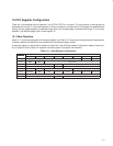
through Fh (the paged registers) is dependent upon which one of eight pages, numbered 0h through 7h, is currently
selected. The selected page is set in base register 7h.
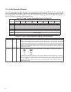
10.1 Base Registers
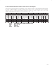
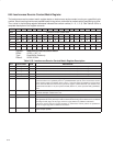
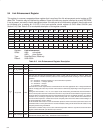
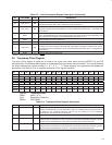
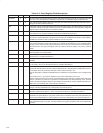
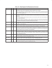
Table 10−1 shows the configuration of the base registers, and Table 10−2 shows the corresponding field descriptions.
The base register field definitions are unaffected by the selected page number.
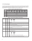
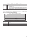
A reserved register or register field (marked as Reserved in the following register configuration tables) is read as 0,
but is subject to future usage. All registers in address pages 2 through 6 are reserved.
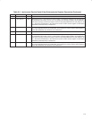
Table 10−1. Base Register Configuration
ADDRESS
BIT POSITION
ADDRESS
0 1 2 3 4 5 6 7
0000 Physical ID R CPS
0001 RHB IBR Gap_Count
0010 Extended (111b) Reserved Total_Ports (0010b)
0011 Max_Speed (010b) Reserved Delay (0000b)
0100 LCtrl C Jitter (000b) Pwr_Class
0101 Watchdog ISBR Loop Pwr_fail Timeout Port_event Enab_accel Enab_multi
0110 Reserved
0111 Page_Select Reserved Port_Select