


4−37
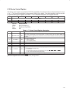
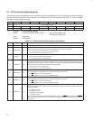
4.50 Serial Bus Control/Status Register
The serial bus control and status register communicates serial bus status information and selects the quick command
protocol. Bit 5 (REQBUSY) in this register must be polled during serial bus byte reads to indicate when data is valid
in the serial bus data register. See Table 4−25 for a complete description of the register contents.
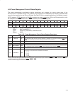
Bit 7 6 5 4 3 2 1 0
Name Serial bus control/status
Type RW R R R RW RW RC RC
Default 0 0 0 0 0 0 0 0
Register: Serial bus control/status
Offset: B3h (function 0)
Type: Read-only, Read/Write, Read/Clear
Default: 00h
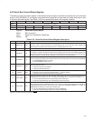
Table 4−25. Serial Bus Control/Status Register Description
BIT SIGNAL TYPE FUNCTION
7 ‡ PROT_SEL RW
Protocol select. When bit 7 is set, the send-byte protocol is used on write requests and the receive-byte
protocol is used on read commands. The word address byte in the serial bus index register (see
Section 4.48) is not output by the PCI7x21/PCI7x11 controller when bit 7 is set.
6 RSVD R Reserved. Bit 6 returns 0 when read.
5 REQBUSY R
Requested serial bus access busy. Bit 5 indicates that a requested serial bus access (byte read or write)
is in progress. A request is made, and bit 5 is set, by writing to the serial bus slave address register (see
Section 4.49). Bit 5 must be polled on reads from the serial interface. After the byte read access has been
completed, this bit is cleared and the read data is valid in the serial bus data register.
4 ROMBUSY R
Serial EEPROM busy status. Bit 4 indicates the status of the PCI7x21/PCI7x11 serial EEPROM circuitry.
Bit 4 is set during the loading of the subsystem ID and other default values from the serial bus EEPROM.
0 = Serial EEPROM circuitry is not busy
1 = Serial EEPROM circuitry is busy
3 ‡ SBDETECT RW
Serial bus detect. When the serial bus interface is detected through a pullup resistor on the SCL terminal
after reset, this bit is set to 1.
0 = Serial bus interface not detected
1 = Serial bus interface detected
2 ‡ SBTEST RW
Serial bus test. When bit 2 is set, the serial bus clock frequency is increased for test purposes.
0 = Serial bus clock at normal operating frequency, 100 kHz (default)
1 = Serial bus clock frequency increased for test purposes
1 ‡ REQ_ERR RC
Requested serial bus access error. Bit 1 indicates when a data error occurs on the serial interface during
a requested cycle and may be set due to a missing acknowledge. Bit 1 is cleared by a writeback of 1.
0 = No error detected during user-requested byte read or write cycle
1 = Data error detected during user-requested byte read or write cycle
0 ‡ ROM_ERR RC
EEPROM data error status. Bit 0 indicates when a data error occurs on the serial interface during the
auto-load from the serial bus EEPROM and may be set due to a missing acknowledge. Bit 0 is also set on
invalid EEPROM data formats. See Section 3.6.4, Serial Bus EEPROM Application, for details on
EEPROM data format. Bit 0 is cleared by a writeback of 1.
0 = No error detected during autoload from serial bus EEPROM
1 = Data error detected during autoload from serial bus EEPROM
‡
This bit is cleared only by the assertion of GRST
.