


2−25
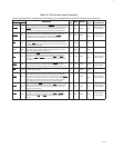
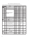
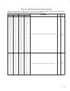
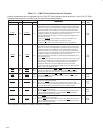
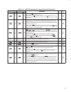
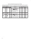
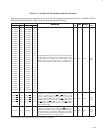
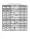
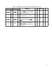
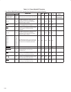
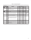
Table 2−14. CardBus PC Card Interface Control Terminals (Continued)
SKT A TERMINAL SKT B TERMINAL
†
DESCRIPTION
I/O
INPUT
OUTPUT
PU/
POWER
NAME NO. NAME NO.
DESCRIPTION
I/O
TYPE
INPUT OUTPUT
PU/
PD
POWER
RAIL
A_CSTOP
A09
B_CSTOP
J17
CardBus stop. CSTOP is driven by a CardBus target
to request the initiator to stop the current CardBus
transaction. CSTOP
is used for target disconnects,
and is commonly asserted by target devices that do
not support burst data transfers.
I/O PCII4 PCIO4 PU3
V
CCA
/
V
CCB
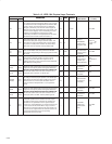
A_CSTSCHG
B02
B_CSTSCHG
F14
CardBus status change. CSTSCHG alerts the system
to a change in the card status, and is used as a
wake-up mechanism.
I PCII6 SW1
V
CCA
/
V
CCB
A_CTRDY
A08
B_CTRDY
H17
CardBus target ready. CTRDY indicates the ability of
the CardBus target to complete the current data
phase of the transaction. A data phase is completed
on a rising edge of CCLK, when both CIRDY
and
CTRDY
are asserted; until this time, wait states are
inserted.
I/O PCII1 PCIO1 PU5
V
CCA
/
V
CCB
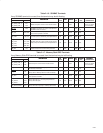
A_CVS1
A_CVS2
A03
E08
B_CVS1
B_CVS2
C18
F19
CardBus voltage sense 1 and CardBus voltage sense
2. CVS1 and CVS2 are used in conjunction with
CCD1
and CCD2 to identify card insertion and
interrogate cards to determine the operating voltage
and card type.
I/O TTLI2 TTLO1 PU4
V
CCA
/
V
CCB
†
These terminals are reserved for the PCI7611 and PCI7411 controllers.