


5−1
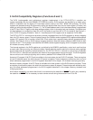
5 ExCA Compatibility Registers (Functions 0 and 1)
The ExCA (exchangeable card architecture) registers implemented in the PCI7x21/PCI7x11 controller are
register-compatible with the Intel 82365SL-DF PCMCIA controller. ExCA registers are identified by an offset value,
which is compatible with the legacy I/O index/data scheme used on the Intel 82365 ISA controller. The ExCA
registers are accessed through this scheme by writing the register offset value into the index register (I/O base), and
reading or writing the data register (I/O base + 1). The I/O base address used in the index/data scheme is programmed
in the PC Card 16-bit I/F legacy mode base address register, which is shared by both card sockets. The offsets from
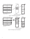
this base address run contiguously from 00h to 3Fh for socket A, and from 40h to 7Fh for socket B. See Figure 5−1
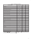
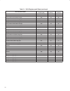
for an ExCA I/O mapping illustration. Table 5−1 identifies each ExCA register and its respective ExCA offset.
The PCI7x21/PCI7x11 controller also provides a memory-mapped alias of the ExCA registers by directly mapping
them into PCI memory space. They are located through the CardBus socket registers/ExCA registers base address
register (PCI register 10h) at memory offset 800h. Each socket has a separate base address programmable by
function. See Figure 5−2 for an ExCA memory mapping illustration. Note that memory offsets are 800h−844h for both
functions 0 and 1. This illustration also identifies the CardBus socket register mapping, which is mapped into the same
4K window at memory offset 0h.
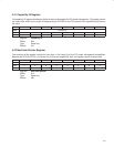
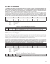
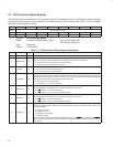
The interrupt registers in the ExCA register set, as defined by the 82365SL specification, control such card functions
as reset, type, interrupt routing, and interrupt enables. Special attention must be paid to the interrupt routing registers
and the host interrupt signaling method selected for the PCI7x21/PCI7x11 controller to ensure that all possible
PCI7x21/PCI7x11 interrupts can potentially be routed to the programmable interrupt controller. The ExCA registers
that are critical to the interrupt signaling are at memory address ExCA offsets 803h and 805h.
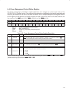
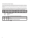
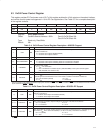
Access to I/O mapped 16-bit PC Cards is available to the host system via two ExCA I/O windows. These are regions
of host I/O address space into which the card I/O space is mapped. These windows are defined by start, end, and
offset addresses programmed in the ExCA registers described in this chapter. I/O windows have byte granularity.
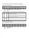
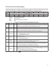
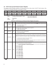
Access to memory-mapped 16-bit PC Cards is available to the host system via five ExCA memory windows. These
are regions of host memory space into which the card memory space is mapped. These windows are defined by start,
end, and offset addresses programmed in the ExCA registers described in this chapter. Memory windows have
4-Kbyte granularity.
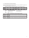
A bit location followed by a
‡ means that this bit is not cleared by the assertion of PRST. This bit is only cleared by
the assertion of GRST
. This is necessary to retain device context during the transition from D3 to D0.