


7−14
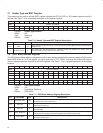
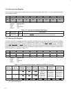
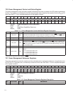
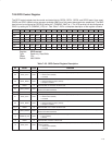
7.20 Power Management Control and Status Register
The power management control and status register implements the control and status of the PCI power-management
function. This register is not affected by the internally generated reset caused by the transition from the D3
hot
to D0
state. See Table 7−17 for a complete description of the register contents.
Bit 15 14 13 12 11 10 9 8 7 6 5 4 3 2 1 0
Name Power management control and status
Type RWC R R R R R R RW R R R R R R RW RW
Default 0 0 0 0 0 0 0 0 0 0 0 0 0 0 0 0
Register: Power management control and status
Offset: 48h
Type: Read/Clear, Read/Write, Read-only
Default: 0000h
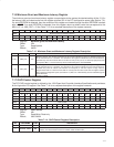
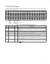
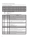
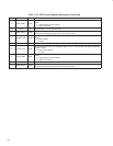
Table 7−17. Power Management Control and Status Register Description
BIT FIELD NAME TYPE DESCRIPTION
15 ‡ PME_STS RWC
Bit 15 is set to 1 when the PCI7x21/PCI7x11 controller normally asserts the PME signal independent
of the state of bit 8 (PME_ENB). This bit is cleared by a writeback of 1, which also clears the PME
signal
driven by the PCI7x21/PCI7x11 controller. Writing a 0 to this bit has no effect.
14−13 DATA_SCALE R This field returns 0s, because the data register is not implemented.
12−9 DATA_SELECT R This field returns 0s, because the data register is not implemented.
8 ‡ PME_ENB RW
When bit 8 is set to 1, PME assertion is enabled. When bit 8 is cleared, PME assertion is disabled. This
bit defaults to 0 if the function does not support PME
generation from D3
cold
. If the function supports
PME
from D3
cold
, then this bit is sticky and must be explicitly cleared by the operating system each
time it is initially loaded.
7−2 RSVD R Reserved. Bits 7−2 return 0s when read.
1−0 ‡ PWR_STATE RW
Power state. This 2-bit field sets the PCI7x21/PCI7x11 controller power state and is encoded as
follows:
00 = Current power state is D0.
01 = Current power state is D1.
10 = Current power state is D2.
11 = Current power state is D3.
‡
These bits are cleared only by the assertion of GRST
.
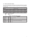
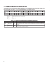
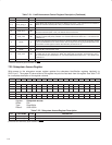
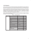
7.21 Power Management Extension Registers
The power management extension register provides extended power-management features not applicable to the
PCI7x21/PCI7x11 controller; thus, it is read-only and returns 0 when read. See Table 7−18 for a complete description
of the register contents.
Bit 15 14 13 12 11 10 9 8 7 6 5 4 3 2 1 0
Name Power management extension
Type R R R R R R R R R R R R R R R R
Default 0 0 0 0 0 0 0 0 0 0 0 0 0 0 0 0
Register: Power management extension
Offset: 4Ah
Type: Read-only
Default: 0000h
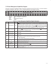
Table 7−18. Power Management Extension Registers Description
BIT FIELD NAME TYPE DESCRIPTION
15−0 RSVD R Reserved. Bits 15−0 return 0s when read.