


7−4
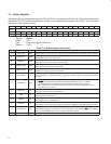
7.4 Status Register
The status register provides status over the PCI7x21/PCI7x11 interface to the PCI bus. All bit functions adhere to the
definitions in the PCI Local Bus Specification, as seen in the following bit descriptions. See Table 7−3 for a complete
description of the register contents.
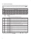
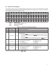
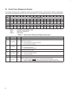
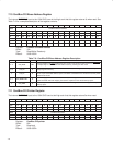
Bit 15 14 13 12 11 10 9 8 7 6 5 4 3 2 1 0
Name Status
Type RCU RCU RCU RCU RCU R R RCU R R R R RU R R R
Default 0 0 0 0 0 0 1 0 0 0 0 1 0 0 0 0
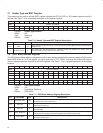
Register: Status
Offset: 06h
Type: Read/Clear/Update, Read-only
Default: 0210h
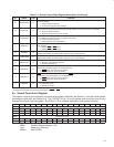
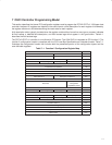
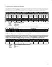
Table 7−3. Status Register Description
BIT FIELD NAME TYPE DESCRIPTION
15 PAR_ERR RCU Detected parity error. Bit 15 is set to 1 when either an address parity or data parity error is detected.
14 SYS_ERR RCU
Signaled system error. Bit 14 is set to 1 when SERR is enabled and the PCI7x21/PCI7x11 controller
has signaled a system error to the host.
13 MABORT RCU
Received master abort. Bit 13 is set to 1 when a cycle initiated by the PCI7x21/PCI7x11 controller on
the PCI bus has been terminated by a master abort.
12 TABORT_REC RCU
Received target abort. Bit 12 is set to 1 when a cycle initiated by the PCI7x21/PCI7x11 controller on
the PCI bus was terminated by a target abort.
11 TABORT_SIG RCU
Signaled target abort. Bit 11 is set to 1 by the PCI7x21/PCI7x11 controller when it terminates a
transaction on the PCI bus with a target abort.
10−9 PCI_SPEED R
DEVSEL timing. Bits 10 and 9 encode the timing of DEVSEL and are hardwired to 01b, indicating that
the PCI7x21/PCI7x11 controller asserts this signal at a medium speed on nonconfiguration cycle
accesses.
8 DATAPAR RCU
Data parity error detected. Bit 8 is set to 1 when the following conditions have been met:
a. PERR
was asserted by any PCI device including the PCI7x21/PCI7x11 controller.
b. The PCI7x21/PCI7x11 controller was the bus master during the data parity error.
c. Bit 6 (PERR_EN) in the command register at offset 04h in the PCI configuration space
(see Section 7.3) is set to 1.
7 FBB_CAP R
Fast back-to-back capable. The PCI7x21/PCI7x11 controller cannot accept fast back-to-back
transactions; therefore, bit 7 is hardwired to 0.
6 UDF R
User-definable features (UDF) supported. The PCI7x21/PCI7x11 controller does not support the UDF;
therefore, bit 6 is hardwired to 0.
5 66MHZ R
66-MHz capable. The PCI7x21/PCI7x11 controller operates at a maximum PCLK frequency of 33
MHz; therefore, bit 5 is hardwired to 0.
4 CAPLIST R
Capabilities list. Bit 4 returns 1 when read, indicating that capabilities additional to standard PCI are
implemented. The linked list of PCI power-management capabilities is implemented in this function.
3 INT_STATUS RU
Interrupt status. This bit reflects the interrupt status of the function. Only when bit 10 (INT_DISABLE)
in the command register (see Section 7.3) is a 0 and this bit is 1, is the function’s INTx
signal asserted.
Setting the INT_DISABLE bit to 1 has no effect on the state of this bit.
2−0 RSVD R Reserved. Bits 3−0 return 0s when read.