


11−11
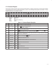
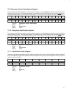
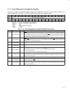
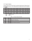
11.17 Power Management Capabilities Register
The power management capabilities register indicates the capabilities of the flash media controller related to PCI
power management. See Table 11−12 for a complete description of the register contents.
Bit 15 14 13 12 11 10 9 8 7 6 5 4 3 2 1 0
Name Power management capabilities
Type RU R R R R R R R R R R R R R R R
Default 0 1 1 1 1 1 1 0 0 0 0 0 0 0 1 0
Register: Power management capabilities
Offset: 46h
Type: Read/Update, Read-only
Default: 7E02h
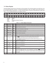
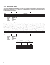
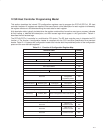
Table 11−12. Power Management Capabilities Register Description
BIT FIELD NAME TYPE DESCRIPTION
15 PME_D3COLD RU
PME support from D3
cold
. This bit can be set to 1 or cleared to 0 via bit 4 (D3_COLD) in the general
control register at offset 4Ch in the PCI configuration space (see Section 11.21). When this bit is set
to 1, it indicates that the controller is capable of generating a PME
wake event from D3
cold
. This bit state
is dependent upon the PCI7x21/PCI7x11 V
AUX
implementation and may be configured by using bit 4
(D3_COLD) in the general control register (see Section 11.21).
14−11 PME_SUPPORT R
PME support. This 4-bit field indicates the power states from which the flash media interface may
assert PME
. This field returns a value of 1111b by default, indicating that PME may be asserted from
the D3
hot
, D2, D1, and D0 power states.
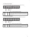
10 D2_SUPPORT R
D2 support. Bit 10 is hardwired to 1, indicating that the flash media controller supports the D2 power
state.
9 D1_SUPPORT R
D1 support. Bit 9 is hardwired to 1, indicating that the flash media controller supports the D1 power
state.
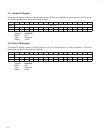
8−6 AUX_CURRENT R
Auxiliary current. This 3-bit field reports the 3.3-V
AUX
auxiliary current requirements. When bit 15
(PME_D3COLD) is cleared, this field returns 000b; otherwise, it returns 001b.
000b = Self-powered
001b = 55 mA (3.3-V
AUX
maximum current required)
5 DSI R
Device-specific initialization. This bit returns 0 when read, indicating that the flash media controller
does not require special initialization beyond the standard PCI configuration header before a generic
class driver is able to use it.
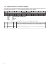
4 RSVD R Reserved. Bit 4 returns 0 when read.
3 PME_CLK R
PME clock. This bit returns 0 when read, indicating that the PCI clock is not required for the flash media
controller to generate PME
.
2−0 PM_VERSION R
Power-management version. This field returns 010b when read, indicating that the flash media
controller is compatible with the registers described in the PCI Bus Power Management Interface
Specification (Revision 1.1).