


12−3
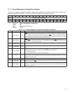
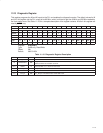
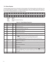
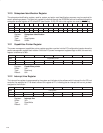
12.3 Command Register
The command register provides control over the SD host controller interface to the PCI bus. All bit functions adhere
to the definitions in the PCI Local Bus Specification, as seen in the following bit descriptions. See Table 12−2 for a
complete description of the register contents.
Bit 15 14 13 12 11 10 9 8 7 6 5 4 3 2 1 0
Name Command
Type R R R R R RW R RW R RW R RW R RW RW R
Default 0 0 0 0 0 0 0 0 0 0 0 0 0 0 0 0
Register: Command
Offset: 04h
Type: Read/Write, Read-only
Default: 0000h
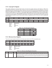
Table 12−2. Command Register Description
BIT FIELD NAME TYPE DESCRIPTION
15−11 RSVD R Reserved. Bits 15−11 return 0s when read.
10 INT_DISABLE RW INTx disable. When set to 1, this bit disables the function from asserting interrupts on the INTx signals.
0 = INTx
assertion is enabled (default)
1 = INTx
assertion is disabled
9 FBB_ENB R Fast back-to-back enable. The SD host controller does not generate fast back-to-back transactions;
therefore, bit 9 returns 0 when read.
8 SERR_ENB RW SERR enable. When bit 8 is set to 1, the SD host controller SERR driver is enabled. SERR can be
asserted after detecting an address parity error on the PCI bus.
7 STEP_ENB R Address/data stepping control. The SD host controller does not support address/data stepping;
therefore, bit 7 is hardwired to 0.
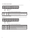
6 PERR_ENB RW Parity error enable. When bit 6 is set to 1, the SD host controller is enabled to drive PERR response
to parity errors through the PERR
signal.
5 VGA_ENB R VGA palette snoop enable. The SD host controller does not feature VGA palette snooping; therefore,
bit 5 returns 0 when read.
4 MWI_ENB RW Memory write and invalidate enable. The SD host controller does not generate memory write invalidate
transactions; therefore, bit 4 returns 0 when read.
3 SPECIAL R Special cycle enable. The SD host controller does not respond to special cycle transactions; therefore,
bit 3 returns 0 when read.
2 MASTER_ENB RW Bus master enable. When bit 2 is set to 1, the SD host controller is enabled to initiate cycles on the
PCI bus.
1 MEMORY_ENB RW Memory response enable. Setting bit 1 to 1 enables the SD host controller to respond to memory cycles
on the PCI bus.
0 IO_ENB R I/O space enable. The SD host controller does not implement any I/O-mapped functionality; therefore,
bit 0 returns 0 when read.