


9−2
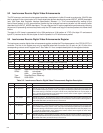
9.2 Isochronous Receive Digital Video Enhancements
The DV frame sync and branch enhancement provides a mechanism in buffer-fill mode to synchronize 1394 DV data
that is received in the correct order to DV frame-sized data buffers described by several INPUT_MORE descriptors
(see 1394 Open Host Controller Interface Specification, Release 1.1). This is accomplished by waiting for the
start-of-frame packet in a DV stream before transferring the received isochronous stream into the memory buffer
described by the INPUT_MORE descriptors. This can improve the DV capture application performance by reducing
the amount of processing overhead required to strip the CIP header and copy the received packets into frame-sized
buffers.
The start of a DV frame is represented in the 1394 packet as a 16-bit pattern of 1FX7h (first byte 1Fh and second
byte X7h) received as the first two bytes of the third quadlet in a DV isochronous packet.
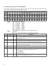
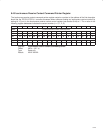
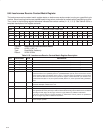
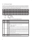
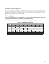
9.3 Isochronous Receive Digital Video Enhancements Register
The isochronous receive digital video enhancements register enables the DV enhancements in the PCI7x21/PCI7x11
controller. The bits in this register may only be modified when both the active (bit 10) and run (bit 15) bits of the
corresponding context control register are 0. See Table 9−2 for a complete description of the register contents.
Bit 31 30 29 28 27 26 25 24 23 22 21 20 19 18 17 16
Name Isochronous receive digital video enhancements
Type R R R R R R R R R R R R R R R R
Default 0 0 0 0 0 0 0 0 0 0 0 0 0 0 0 0
Bit 15 14 13 12 11 10 9 8 7 6 5 4 3 2 1 0
Name Isochronous receive digital video enhancements
Type R R RSC RSC R R RSC RSC R R RSC RSC R R RSC RSC
Default 0 0 0 0 0 0 0 0 0 0 0 0 0 0 0 0
Register: Isochronous receive digital video enhancements
Offset: A80h set register
A84h clear register
Type: Read/Set/Clear, Read-only
Default: 0000 0000h
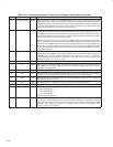
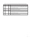
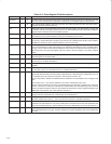
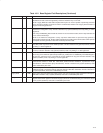
Table 9−2. Isochronous Receive Digital Video Enhancements Register Description
BIT FIELD NAME TYPE DESCRIPTION
31−14 RSVD R Reserved. Bits 31−14 return 0s when read.
13 DV_Branch3 RSC When bit 13 is set to 1, the isochronous receive context 3 synchronizes reception to the DV frame start
tag in bufferfill mode if input_more.b = 01b, and jumps to the descriptor pointed to by frameBranch if
a DV frame start tag is received out of place. This bit is only interpreted when bit 12 (CIP_Strip3) is
set to 1 and bit 30 (isochHeader) in the isochronous receive context control register at OHCI offset
460h/464h (see Section 8.44) is cleared to 0.
12 CIP_Strip3 RSC When bit 12 is set to 1, the isochronous receive context 3 strips the first two quadlets of payload. This
bit is only interpreted when bit 30 (isochHeader) in the isochronous receive context control register at
OHCI offset 460h/464h (see Section 8.44) is cleared to 0.
11−10 RSVD R Reserved. Bits 11 and 10 return 0s when read.
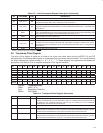
9 DV_Branch2 RSC When bit 9 is set to 1, the isochronous receive context 2 synchronizes reception to the DV frame start
tag in bufferfill mode if input_more.b = 01b, and jumps to the descriptor pointed to by frameBranch if
a DV frame start tag is received out of place. This bit is only interpreted when bit 8 (CIP_Strip2) is set
to 1 and bit 30 (isochHeader) in the isochronous receive context control register at OHCI offset
440h/444h (see Section 8.44) is cleared to 0.
8 CIP_Strip2 RSC When bit 8 is set to 1, the isochronous receive context 2 strips the first two quadlets of payload. This
bit is only interpreted when bit 30 (isochHeader) in the isochronous receive context control register at
OHCI offset 440h/444h (see Section 8.44) is cleared to 0.