


8−13
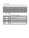
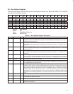
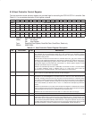
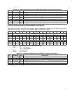
8.16 Host Controller Control Register
The host controller control set/clear register pair provides flags for controlling the PCI7x21/PCI7x11 controller. See
Table 8−11 for a complete description of the register contents.
Bit 31 30 29 28 27 26 25 24 23 22 21 20 19 18 17 16
Name Host controller control
Type RSU RSC RSC R R R R R R RSC R R RSC RSC RSC RSCU
Default 0 X 0 0 0 0 0 0 1 0 0 0 0 X 0 0
Bit 15 14 13 12 11 10 9 8 7 6 5 4 3 2 1 0
Name Host controller control
Type R R R R R R R R R R R R R R R R
Default 0 0 0 0 0 0 0 0 0 0 0 0 0 0 0 0
Register: Host controller control
Offset: 50h set register
54h clear register
Type: Read/Set/Clear/Update, Read/Set/Clear, Read/Clear, Read-only
Default: X08X 0000h
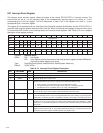
Table 8−11. Host Controller Control Register Description
BIT FIELD NAME TYPE DESCRIPTION
31 BIBimage Valid RSU When bit 31 is set to 1, the PCI7x21/PCI7x11 physical response unit is enabled to respond to block
read requests to host configuration ROM and to the mechanism for atomically updating
configuration ROM. Software creates a valid image of the bus_info_block in host configuration
ROM before setting this bit.
When this bit is cleared, the PCI7x21/PCI7x11 controller returns ack_type_error on block read
requests to host configuration ROM. Also, when this bit is cleared and a 1394 bus reset occurs,
the configuration ROM mapping register at OHCI offset 34h (see Section 8.12), configuration
ROM header register at OHCI offset 18h (see Section 8.7), and bus options register at OHCI
offset 20h (see Section 8.9) are not updated.
Software can set this bit only when bit 17 (linkEnable) is 0. Once bit 31 is set to 1, it can be cleared
by a system (hardware) reset, a software reset, or if a fetch error occurs when the
PCI7x21/PCI7x11 controller loads bus_info_block registers from host memory.
30 noByteSwapData RSC Bit 30 controls whether physical accesses to locations outside the PCI7x21/PCI7x11 controller
itself, as well as any other DMA data accesses are byte swapped.
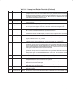
29 AckTardyEnable RSC Bit 29 controls the acknowledgement of ack_tardy. When bit 29 is set to 1, ack_tardy may be
returned as an acknowledgment to accesses from the 1394 bus to the PCI7x21/PCI7x11
controller, including accesses to the bus_info_block. The PCI7x21/PCI7x11 controller returns
ack_tardy to all other asynchronous packets addressed to the PCI7x21/PCI7x11 node. When the
PCI7x21/PCI7x11 controller sends ack_tardy, bit 27 (ack_tardy) in the interrupt event register at
OHCI offset 80h/84h (see Section 8.21) is set to 1 to indicate the attempted asynchronous
access.
Software ensures that bit 27 (ack_tardy) in the interrupt event register is 0. Software also unmasks
wake-up interrupt events such as bit 19 (phy) and bit 27 (ack_tardy) in the interrupt event register
before placing the PCI7x21/PCI7x11 controller into the D1 power mode.
Software must not set this bit if the PCI7x21/PCI7x11 node is the 1394 bus manager.
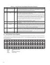
28−24 RSVD R Reserved. Bits 28−24 return 0s when read.
23 ‡ programPhyEnable R Bit 23 informs upper-level software that lower-level software has consistently configured the IEEE
1394a-2000 enhancements in the link and PHY layers. When this bit is 1, generic software such
as the OHCI driver is responsible for configuring IEEE 1394a-2000 enhancements in the PHY
layer and bit 22 (aPhyEnhanceEnable). When this bit is 0, the generic software may not modify
the IEEE 1394a-2000 enhancements in the PHY layer and cannot interpret the setting of bit 22
(aPhyEnhanceEnable). This bit is initialized from serial EEPROM. This bit defaults to 1.
‡
This bit is cleared only by the assertion of GRST
.