


8−40
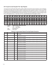
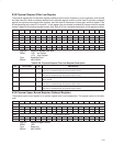
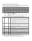
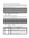
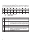
8.42 Isochronous Transmit Context Control Register
The isochronous transmit context control set/clear register controls options, state, and status for the isochronous
transmit DMA contexts. The n value in the following register addresses indicates the context number (n = 0, 1, 2, 3,
…, 7). See Table 8−33 for a complete description of the register contents.
Bit 31 30 29 28 27 26 25 24 23 22 21 20 19 18 17 16
Name Isochronous transmit context control
Type RSCU RSC RSC RSC RSC RSC RSC RSC RSC RSC RSC RSC RSC RSC RSC RSC
Default X X X X X X X X X X X X X X X X
Bit 15 14 13 12 11 10 9 8 7 6 5 4 3 2 1 0
Name Isochronous transmit context control
Type RSC R R RSU RU RU R R RU RU RU RU RU RU RU RU
Default 0 0 0 X 0 0 0 0 X X X X X X X X
Register: Isochronous transmit context control
Offset: 200h + (16 * n) set register
204h + (16 * n) clear register
Type: Read/Set/Clear/Update, Read/Set/Clear, Read/Set/Update, Read/Update, Read-only
Default: XXXX X0XXh
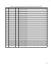
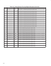
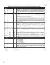
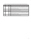
Table 8−33. Isochronous Transmit Context Control Register Description
BIT FIELD NAME TYPE DESCRIPTION
31 cycleMatchEnable RSCU When bit 31 is set to 1, processing occurs such that the packet described by the context first
descriptor block is transmitted in the cycle whose number is specified in the cycleMatch field
(bits 30−16). The cycleMatch field (bits 30−16) must match the low-order two bits of cycleSeconds
and the 13-bit cycleCount field in the cycle start packet that is sent or received immediately before
isochronous transmission begins. Since the isochronous transmit DMA controller may work ahead,
the processing of the first descriptor block may begin slightly in advance of the actual cycle in which
the first packet is transmitted.
The effects of this bit, however, are impacted by the values of other bits in this register and are
explained in the 1394 Open Host Controller Interface Specification. Once the context has become
active, hardware clears this bit.
30−16 cycleMatch RSC This field contains a 15-bit value, corresponding to the low-order two bits of the isochronous cycle
timer register at OHCI offset F0h (see Section 8.34) cycleSeconds field (bits 31−25) and the
cycleCount field (bits 24−12). If bit 31 (cycleMatchEnable) is set to 1, then this isochronous transmit
DMA context becomes enabled for transmits when the low-order two bits of the isochronous cycle
timer register at OHCI offset F0h cycleSeconds field (bits 31−25) and the cycleCount field
(bits 24−12) value equal this field (cycleMatch) value.
15 run RSC Bit 15 is set to 1 by software to enable descriptor processing for the context and cleared by software
to stop descriptor processing. The PCI7x21/PCI7x11 controller changes this bit only on a system
(hardware) or software reset.
14−13 RSVD R Reserved. Bits 14 and 13 return 0s when read.
12 wake RSU Software sets bit 12 to 1 to cause the PCI7x21/PCI7x11 controller to continue or resume descriptor
processing. The PCI7x21/PCI7x11 controller clears this bit on every descriptor fetch.
11 dead RU The PCI7x21/PCI7x11 controller sets bit 11 to 1 when it encounters a fatal error, and clears the bit
when software clears bit 15 (run) to 0.
10 active RU The PCI7x21/PCI7x11 controller sets bit 10 to 1 when it is processing descriptors.
9−8 RSVD R Reserved. Bits 9 and 8 return 0s when read.
7−5 spd RU This field in not meaningful for isochronous transmit contexts.
4−0 event code RU Following an OUTPUT_LAST* command, the error code is indicated in this field. Possible values are:
ack_complete, evt_descriptor_read, evt_data_read, and evt_unknown.
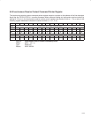
†
On an overflow for each running context, the isochronous transmit DMA supports up to 7 cycle skips, when the following are true:
1. Bit 11 (dead) in either the isochronous transmit or receive context control register is set to 1.
2. Bits 4−0 (eventcode field) in either the isochronous transmit or receive context control register is set to evt_timeout.
3. Bit 24 (unrecoverableError) in the interrupt event register at OHCI offset 80h/84h (see Section 8.21) is set to 1.