


8−8
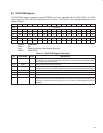
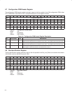
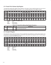
8.7 Configuration ROM Header Register
The configuration ROM header register externally maps to the first quadlet of the 1394 configuration ROM, offset
FFFF F000 0400h. See Table 8−6 for a complete description of the register contents.
Bit 31 30 29 28 27 26 25 24 23 22 21 20 19 18 17 16
Name Configuration ROM header
Type RW RW RW RW RW RW RW RW RW RW RW RW RW RW RW RW
Default 0 0 0 0 0 0 0 0 0 0 0 0 0 0 0 0
Bit 15 14 13 12 11 10 9 8 7 6 5 4 3 2 1 0
Name Configuration ROM header
Type RW RW RW RW RW RW RW RW RW RW RW RW RW RW RW RW
Default X X X X X X X X X X X X X X X X
Register: Configuration ROM header
Offset: 18h
Type: Read/Write
Default: 0000 XXXXh
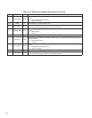
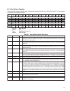
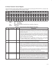
Table 8−6. Configuration ROM Header Register Description
BIT FIELD NAME TYPE DESCRIPTION
31−24 info_length RW IEEE 1394 bus-management field. Must be valid when bit 17 (linkEnable) in the host controller control
register at OHCI offset 50h/54h (see Section 8.16) is set to 1. The default value for this field is 00h.
23−16 crc_length RW IEEE 1394 bus-management field. Must be valid when bit 17 (linkEnable) in the host controller control
register at OHCI offset 50h/54h (see Section 8.16) is set to 1. The default value for this field is 00h.
15−0 rom_crc_value RW IEEE 1394 bus-management field. Must be valid at any time bit 17 (linkEnable) in the host controller
control register at OHCI offset 50h/54h (see Section 8.16) is set to 1.
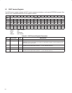
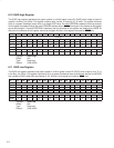
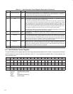
8.8 Bus Identification Register
The bus identification register externally maps to the first quadlet in the Bus_Info_Block and contains the constant
3133 3934h, which is the ASCII value of 1394.
Bit 31 30 29 28 27 26 25 24 23 22 21 20 19 18 17 16
Name Bus identification
Type R R R R R R R R R R R R R R R R
Default 0 0 1 1 0 0 0 1 0 0 1 1 0 0 1 1
Bit 15 14 13 12 11 10 9 8 7 6 5 4 3 2 1 0
Name Bus identification
Type R R R R R R R R R R R R R R R R
Default 0 0 1 1 1 0 0 1 0 0 1 1 0 1 0 0
Register: Bus identification
Offset: 1Ch
Type: Read-only
Default: 3133 3934h