


5−9
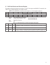
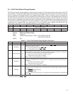
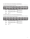
5.5 ExCA Card Status-Change Register
The ExCA card status-change register controls interrupt routing for I/O interrupts as well as other critical 16-bit PC
Card functions. The register enables these interrupt sources to generate an interrupt to the host. When the interrupt
source is disabled, the corresponding bit in this register always reads 0. When an interrupt source is enabled, the
corresponding bit in this register is set to indicate that the interrupt source is active. After generating the interrupt to
the host, the interrupt service routine must read this register to determine the source of the interrupt. The interrupt
service routine is responsible for resetting the bits in this register as well. Resetting a bit is accomplished by one of
two methods: a read of this register or an explicit writeback of 1 to the status bit. The choice of these two methods
is based on bit 2 (interrupt flag clear mode select) in the ExCA global control register (CB offset 81Eh, see
Section 5.20). See Table 5−7 for a complete description of the register contents.
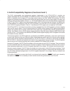
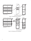
Bit 7 6 5 4 3 2 1 0
Name ExCA card status-change
Type R R R R R R R R
Default 0 0 0 0 0 0 0 0
Register: ExCA card status-change
Type: Read-only
Offset: CardBus socket address + 804h; Card A ExCA offset 04h
Card B ExCA offset 44h
Default: 00h
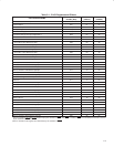
Table 5−7. ExCA Card Status-Change Register Description
BIT SIGNAL TYPE FUNCTION
7−4 RSVD R Reserved. Bits 7−4 return 0s when read.
3 † CDCHANGE R
Card detect change. Bit 3 indicates whether a change on CD1 or CD2 occurred at the PC Card
interface. This bit is encoded as:
0 = No change detected on either CD1 or CD2
1 = Change detected on either CD1 or CD2
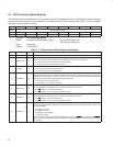
2 † READYCHANGE R
Ready change. When a 16-bit memory is installed in the socket, bit 2 includes whether the source of
a PCI7x21/PCI7x11 interrupt was due to a change on READY at the PC Card interface, indicating that
the PC Card is now ready to accept new data. This bit is encoded as:
0 = No low-to-high transition detected on READY (default)
1 = Detected low-to-high transition on READY
When a 16-bit I/O card is installed, bit 2 is always 0.
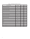
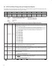
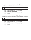
1 † BATWARN R
Battery warning change. When a 16-bit memory card is installed in the socket, bit 1 indicates whether
the source of a PCI7x21/PCI7x11 interrupt was due to a battery-low warning condition. This bit is
encoded as:
0 = No battery warning condition (default)
1 = Detected battery warning condition
When a 16-bit I/O card is installed, bit 1 is always 0.
0 † BATDEAD R
Battery dead or status change. When a 16-bit memory card is installed in the socket, bit 0 indicates
whether the source of a PCI7x21/PCI7x11 interrupt was due to a battery dead condition. This bit is
encoded as:
0 = STSCHG
deasserted (default)
1 = STSCHG
asserted
Ring indicate. When the PCI7x21/PCI7x11 is configured for ring indicate operation, bit 0 indicates the
status of RI
.
†
These are PME context bits and can be cleared only by the assertion of GRST
when PME is enabled. If PME is not enabled, then these bits are
cleared by the assertion of PRST
or GRST.