


13−3
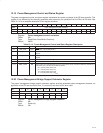
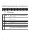
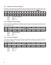
13.3 Command Register
The command register provides control over the Smart Card controller interface to the PCI bus. All bit functions
adhere to the definitions in the PCI Local Bus Specification, as seen in the following bit descriptions. The SERR_EN
and PERR_EN enable bits in this register are internally wired-OR between other functions, and these control bits
appear separately according to their software function. See Table 13−2 for a complete description of the register
contents.
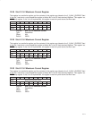
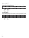
Bit 15 14 13 12 11 10 9 8 7 6 5 4 3 2 1 0
Name Command
Type R R R R R RW R RW R RW R R R R RW R
Default 0 0 0 0 0 0 0 0 0 0 0 0 0 0 0 0
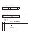
Register: Command
Offset: 04h
Type: Read/Write, Read-only
Default: 0000h
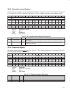
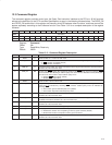
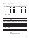
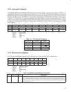
Table 13−2. Command Register Description
BIT FIELD NAME TYPE DESCRIPTION
15−11 RSVD R Reserved. Bits 15−11 return 0s when read.
10 INT_DIS RW INTx disable. When set to 1, this bit disables the function from asserting interrupts on the INTx signals.
0 = INTx
assertion is enabled (default)
1 = INTx
assertion is disabled
9 FBB_EN R Fast back-to-back enable. The Smart Card interface does not generate fast back-to-back transactions;
therefore, bit 9 returns 0 when read.
8 SER_EN RW System error (SERR) enable. Bit 8 controls the enable for the SERR driver on the PCI interface. SERR
can be asserted after detecting an address parity error on the PCI bus. Both bits 8 and 6 (PERR_EN)
must be set for this function to report address parity errors.
0 = Disable SERR output driver (default)
1 = Enable SERR
output driver
7 RSVD R Reserved. Bit 7 returns 0 when read.
6 PERR_EN RW Parity error response enable. Bit 6 controls this function response to parity errors through PERR. Data
parity errors are indicated by asserting PERR
, whereas address parity errors are indicated by
asserting SERR
.
0 = This function ignores detected parity error (default)
1 = This function responds to detected parity errors
5 VGA_EN R VGA palette snoop enable. The Smart Card interface does not feature VGA palette snooping;
therefore, bit 5 returns 0 when read.
4 MWI_EN R Memory write and invalidate enable. The Smart Card controller does not generate memory write
invalidate transactions; therefore, bit 4 returns 0 when read.
3 SPECIAL R Special cycle enable. The Smart Card interface does not respond to special cycle transactions;
therefore, bit 3 returns 0 when read.
2 MAST_EN R Bus master enable. This function is target only.
1 MEM_EN RW Memory space enable. This bit controls memory access.
0 = Disables this function from responding to memory space accesses (default)
1 = Enables this function to respond to memory space accesses
0 IO_EN R I/O space enable. The Smart Card interface does not implement any I/O-mapped functionality;
therefore, bit 0 returns 0 when read.