


3−9
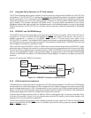
3.5.7 Integrated Pullup Resistors for PC Card Interface
The PC Card Standard requires pullup resistors on various terminals to support both CardBus and 16-bit PC Card
configurations. The PCI7x21/PCI7x11 controller has integrated all of these pullup resistors and requires no additional
external components. The I/O buffer on the BVD1(STSCHG
)/CSTSCHG terminal has the capability to switch to an
internal pullup resistor when a 16-bit PC Card is inserted, or switch to an internal pulldown resistor when a CardBus
card is inserted. This prevents inadvertent CSTSCHG events. The pullup resistor requirements for the various
UltraMedia interfaces are either included in the UltraMedia cards (or the UltraMedia adapter) or are part of the existing
PCMCIA architecture. The PCI7x21/PCI7x11 controller does not require any additional components for UltraMedia
support.
3.5.8 SPKROUT and CAUDPWM Usage
The SPKROUT terminal carries the digital audio signal from the PC Card to the system. When a 16-bit PC Card is
configured for I/O mode, the BVD2 terminal becomes the SPKR
input terminal from the card. This terminal, in
CardBus applications, is referred to as CAUDIO. SPKR
passes a TTL-level binary audio signal to the
PCI7x21/PCI7x11 controller. The CardBus CAUDIO signal also can pass a single-amplitude binary waveform as well
as a PWM signal. The binary audio signal from each PC Card sockets is enabled by bit 1 (SPKROUTEN) of the card
control register (PCI offset 91h, see Section 4.38).
Older controllers support CAUDIO in binary or PWM mode, but use the same output terminal (SPKROUT). Some
audio chips may not support both modes on one terminal and may have a separate terminal for binary and PWM.
The PCI7x21/PCI7x11 implementation includes a signal for PWM, CAUDPWM, which can be routed to an MFUNC
terminal. Bit 2 (AUD2MUX), located in the card control register, is programmed to route a CardBus CAUDIO PWM
terminal to CAUDPWM. See Section 4.36, Multifunction Routing Register, for details on configuring the MFUNC
terminals.
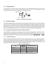
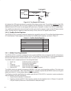
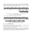
Figure 3−5 illustrates the SPKROUT connection.
Speaker
Subsystem
BINARY_SPKR
System
Core Logic
PCI7x21/
PCI7x11
CAUDPWM
SPKROUT
PWM_SPKR
Figure 3−5. SPKROUT Connection to Speaker Driver
3.5.9 LED Socket Activity Indicators
The socket activity LEDs are provided to indicate when a PC Card is being accessed. The LEDA1 and LEDA2 signals
can be routed to the multifunction terminals. When configured for LED outputs, these terminals output an active high
signal to indicate socket activity. LEDA1 indicates socket A (card A) activity, and LEDA2 indicates socket B (card B)
activity. The LED_SKT output indicates socket activity to either socket A or socket B. See Section 4.36, Multifunction
Routing Status Register,
for details on configuring the multifunction terminals.
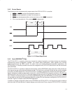
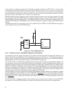
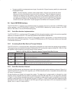
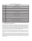
The active-high LED signal is driven for 64 ms. When the LED is not being driven high, it is driven to a low state. Either
of the two circuits shown in Figure 3−6 can be implemented to provide LED signaling, and the board designer must
implement the circuit that best fits the application.
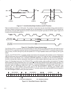
The LED activity signals are valid when a card is inserted, powered, and not in reset. For PC Card-16, the LED activity
signals are pulsed when READY(IREQ
) is low. For CardBus cards, the LED activity signals are pulsed if CFRAME,
IRDY
, or CREQ are active.