


13−15
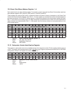
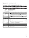
13.25 Smart Card Configuration 1 Register
BIOS or EEPROM configure system dependent Smart Card interface information through this register. Information
of this register can be read from the Smart Card configuration 1 alias register in the Smart Card global control register
set. The software utilizes this information and adjusts the software and firmware behavior if necessary.
Corresponding bits are tied to 0 if the socket is not implemented.
Class A and B support are depend on the system and integrated device. Supporting both classes requires method
(pins) to control 5.0 V and 3.0 V.
Default value and bit types are depending on the device. When this core is integrated into a device and does not have
all four sockets, removed sockets bits must be tied to 0 and changed to read-only bits.
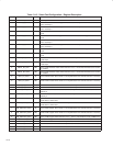
See Table 13−15 for a complete description of the register contents. All bits in this register are reset by GRST only.
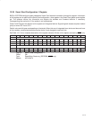
Bit 31 30 29 28 27 26 25 24 23 22 21 20 19 18 17 16
Name Smart Card configuration 1
Type RW RW RW RW R RW RW RW R RW RW RW R RW RW RW
Default 0 0 0 0 0 0 1 1 0 1 1 1 0 1 0 0
Bit 15 14 13 12 11 10 9 8 7 6 5 4 3 2 1 0
Name Smart Card configuration 1
Type R RW RW RW R R R R R RW RW RW R RW RW RW
Default 0 0 1 1 0 0 1 1 0 0 0 0 0 1 1 1
Register: Smart Card configuration 1
Offset: 58h
Type: Read/Write, Read-only (EEPROM, GRST
only)
Default: 0374 3307h