


6−5
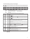
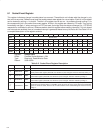
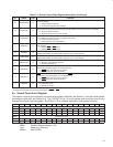
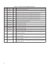
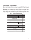
Table 6−4. Socket Present State Register Description (Continued)
BIT SIGNAL TYPE FUNCTION
9 † BADVCCREQ R
Bad V
CC
request. This bit indicates that the host software has requested that the socket be powered at
an invalid voltage.
0 = Normal operation (default)
1 = Invalid V
CC
request by host software
8 † DATALOST R
Data lost. This bit indicates that a PC Card removal event may have caused lost data because the cycle
did not terminate properly or because write data still resides in the PCI7x21/PCI7x11 controller.
0 = Normal operation (default)
1 = Potential data loss due to card removal
7 † NOTACARD R
Not a card. This bit indicates that an unrecognizable PC Card has been inserted in the socket. This bit is
not updated until a valid PC Card is inserted into the socket.
0 = Normal operation (default)
1 = Unrecognizable PC Card detected
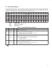
6 IREQCINT R
READY(IREQ)//CINT. This bit indicates the current status of the READY(IREQ)//CINT signal at the PC
Card interface.
0 = READY(IREQ
)//CINT is low.
1 = READY(IREQ
)//CINT is high.
5 † CBCARD R
CardBus card detected. This bit indicates that a CardBus PC Card is inserted in the socket. This bit is not
updated until another card interrogation sequence occurs (card insertion).
4 † 16BITCARD R
16-bit card detected. This bit indicates that a 16-bit PC Card is inserted in the socket. This bit is not
updated until another card interrogation sequence occurs (card insertion).
3 † PWRCYCLE R
Power cycle. This bit indicates the status of each card powering request. This bit is encoded as:
0 = Socket is powered down (default).
1 = Socket is powered up.
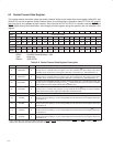
2 † CDETECT2 R
CCD2. This bit reflects the current status of the CCD2 signal at the PC Card interface. Changes to this
signal during card interrogation are not reflected here.
0 = CCD2 is low (PC Card may be present)
1 = CCD2
is high (PC Card not present)
1 † CDETECT1 R
CCD1. This bit reflects the current status of the CCD1 signal at the PC Card interface. Changes to this
signal during card interrogation are not reflected here.
0 = CCD1 is low (PC Card may be present).
1 = CCD1
is high (PC Card not present).
0 CARDSTS R
CSTSCHG. This bit reflects the current status of the CSTSCHG signal at the PC Card interface.
0 = CSTSCHG is low.
1 = CSTSCHG is high.
†
One or more bits in the register are PME context bits and can be cleared only by the assertion of GRST
when PME is enabled. If PME is not
enabled, then these bits are cleared by the assertion of PRST
or GRST.
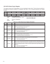
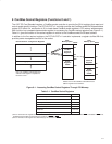
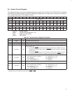
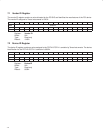
6.4 Socket Force Event Register
This register is used to force changes to the socket event register (offset 00h, see Section 6.1) and the socket present
state register (offset 08h, see Section 6.3). The CVSTEST bit (bit 14) in this register must be written when forcing
changes that require card interrogation. See Table 6−5 for a complete description of the register contents.
Bit 31 30 29 28 27 26 25 24 23 22 21 20 19 18 17 16
Name Socket force event
Type R R R R R R R R R R R R R R R R
Default 0 0 0 0 0 0 0 0 0 0 0 0 0 0 0 0
Bit 15 14 13 12 11 10 9 8 7 6 5 4 3 2 1 0
Name Socket force event
Type R W W W W W W W W R W W W W W W
Default X X X X X X X X X X X X X X X X
Register: Socket force event
Offset: CardBus Socket Address + 0Ch
Type: Read-only, Write-only
Default: 0000 XXXXh