


13−10
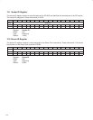
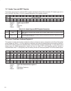
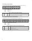
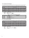
13.16 Maximum Latency Register
The maximum latency register contains the maximum latency value for the Smart Card controller core.
Bit 7 6 5 4 3 2 1 0
Name Maximum latency
Type RU RU RU RU RU RU RU RU
Default 0 0 0 0 0 0 0 0
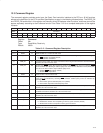
Register: Maximum latency
Offset: 3Fh
Type: Read/Update
Default: 00h
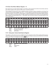
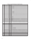
Table 13−9. Maximum Latency Register Description
BIT FIELD NAME TYPE DESCRIPTION
7−0 MAX_LAT RU Maximum latency. The contents of this field may be used by host BIOS to assign an arbitration priority level
to the Smart Card controller. The default for this register indicates that the Smart Card controller may need
to access the PCI bus as often as every 0.25 µs; thus, an extremely high priority level is requested. The
contents of this field may also be loaded through the serial EEPROM.
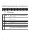
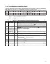
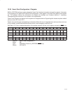
13.17 Capability ID and Next Item Pointer Registers
The capability ID and next item pointer register identifies the linked-list capability item and provides a pointer to the
next capability item. See Table 13−10 for a complete description of the register contents.
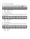
Bit 15 14 13 12 11 10 9 8 7 6 5 4 3 2 1 0
Name Capability ID and next item pointer
Type R R R R R R R R R R R R R R R R
Default 0 0 0 0 0 0 0 0 0 0 0 0 0 0 0 1
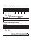
Register: Capability ID and next item pointer
Offset: 44h
Type: Read-only
Default: 0001h
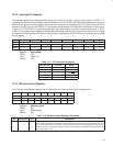
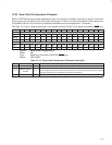
Table 13−10. Capability ID and Next Item Pointer Registers Description
BIT FIELD NAME TYPE DESCRIPTION
15−8 NEXT_ITEM R Next item pointer. The Smart Card controller supports only one additional capability, PCI power
management, that is communicated to the system through the extended capabilities list; therefore,
this field returns 00h when read.
7−0 CAPABILITY_ID R Capability identification. This field returns 01h when read, which is the unique ID assigned by the PCI
SIG for PCI power-management capability.