


2−17
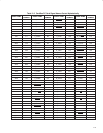
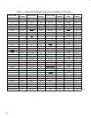
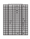
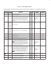
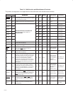
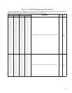
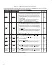
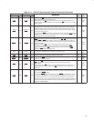
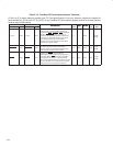
Table 2−8. PCI Interface Control Terminals
Internal pullup/pulldown resistors and pin strapping are not applicable for the PCI interface control terminals.
TERMINAL
DESCRIPTION
I/O
INPUT
OUTPUT
POWER
EXTERNAL
NAME NO.
DESCRIPTION
I/O
TYPE
INPUT OUTPUT
POWER
RAIL
EXTERNAL
COMPONENTS
DEVSEL
N08
PCI device select. The controller asserts DEVSEL to claim a PCI cycle
as the target device. As a PCI initiator on the bus, the controller monitors
DEVSEL
until a target responds. If no target responds before timeout
occurs, then the controller terminates the cycle with an initiator abort.
I/O PCII3 PCIO3 V
CCP
Pullup resistor per
PCI specification
FRAME
V07
PCI cycle frame. FRAME is driven by the initiator of a bus cycle. FRAME
is asserted to indicate that a bus transaction is beginning, and data
transfers continue while this signal is asserted. When FRAME
is
deasserted, the PCI bus transaction is in the final data phase.
I/O PCII3 PCIO3 V
CCP
Pullup resistor per
PCI specification
GNT
T02
PCI bus grant. GNT is driven by the PCI bus arbiter to grant the
controller access to the PCI bus after the current data transaction has
completed. GNT
may or may not follow a PCI bus request, depending on
the PCI bus parking algorithm.
I PCII3 V
CCP
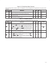
IDSEL W05
Initialization device select. IDSEL selects the controller during
configuration space accesses. IDSEL can be connected to one of the
upper 24 PCI address lines on the PCI bus.
I PCII3 V
CCP
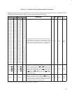
IRDY
U07
PCI initiator ready. IRDY indicates the ability of the PCI bus initiator to
complete the current data phase of the transaction. A data phase is
completed on a rising edge of PCLK where both IRDY
and TRDY are
asserted. Until IRDY
and TRDY are both sampled asserted, wait states
are inserted.
I/O PCII3 PCIO3 V
CCP
Pullup resistor per
PCI specification
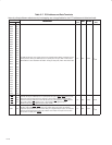
PERR
V08
PCI parity error indicator. PERR is driven by a PCI controller to indicate
that calculated parity does not match PAR when PERR
is enabled
through bit 6 of the command register (PCI offset 04h, see Section 4.4).
I/O PCII3 PCIO3 V
CCP
Pullup resistor per
PCI specification
REQ
U01
PCI bus request. REQ is asserted by the controller to request access to
the PCI bus as an initiator.
O PCIO3 V
CCP
SERR
U08
PCI system error. SERR is an output that is pulsed from the controller
when enabled through bit 8 of the command register (PCI offset 04h,
see Section 4.4) indicating a system error has occurred. The controller
need not be the target of the PCI cycle to assert this signal. When SERR
is enabled in the command register, this signal also pulses, indicating
that an address parity error has occurred on a CardBus interface.
O PCIO3 V
CCP
Pullup resistor per
PCI specification
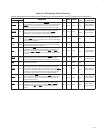
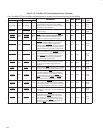
STOP
W08
PCI cycle stop signal. STOP is driven by a PCI target to request the
initiator to stop the current PCI bus transaction. STOP
is used for target
disconnects and is commonly asserted by target devices that do not
support burst data transfers.
I/O PCII3 PCIO3 V
CCP
Pullup resistor per
PCI specification
TRDY
R08
PCI target ready. TRDY indicates the ability of the primary bus target to
complete the current data phase of the transaction. A data phase is
completed on a rising edge of PCLK when both IRDY
and TRDY are
asserted. Until both IRDY
and TRDY are asserted, wait states are
inserted.
I/O PCII3 PCIO3 V
CCP
Pullup resistor per
PCI specification