


SETUP Menu Teledyne API - T100 UV Fluorescence SO2 Analyzer
112
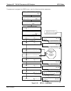
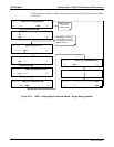
5.9.3. ANALOG I/O CONFIGURATION
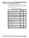
Table 6-8 lists the analog I/O functions that are available in the T100.
Table 5-4: DIAG - Analog I/O Functions
SUB MENU FUNCTION
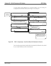
AOUTS CALIBRATED: Shows the status of the analog output calibration (YES/NO) and initiates a calibration of all
analog output channels.
CONC_OUT_1
Sets the basic electronic configuration of the A1 analog output (SO
2
). There are three options:
RANGE: Selects the signal type (voltage or current loop) and full scale level of the
output.
REC_OFS: Allows setting a voltage offset (not available when RANGE is set to Current
Loop (CURR).
AUTO_CAL: Performs the same calibration as AOUT CALIBRATED, but on this one
channel only.
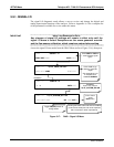
NOTE: Any change to RANGE or REC_OFS requires recalibration of this output.
CONC_OUT_2
Same as for CONC_OUT_1 but for analog channel 2 (SO
2
)
TEST OUTPUT
Same as for CONC_OUT_1 but for analog channel 3 (TEST)
CONC_OUT_3
(Not available in the analyzer’s standard configuration; applies when optional sensor installed).
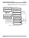
AIN CALIBRATED
Shows the calibration status (YES/NO) and initiates a calibration of the analog input channels.
XIN1
.
.
.
XIN8
For each of 8 external analog inputs channels, shows the gain, offset, engineering units, and
whether the channel is to show up as a Test function.
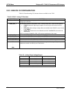
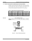
Table 5-5: Analog Output Voltage Ranges
RANGE MINIMUM OUTPUT MAXIMUM OUTPUT
0-0.1 V -5 mV +105 mV
0-1 V -0.05 V +1.05 V
0-5 V -0.25 V +5.25 V
0-10 V -0.5 V +10.5 V
The default offset for all ranges is 0 VDC.
06807C DCN6650