


Teledyne API - T100 UV Fluorescence SO2 Analyzer EPA Protocol Calibration
217
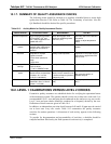
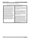
10.3. ZERO AND SPAN CHECKS
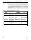
A system of Level 1 and Level 2 zero span checks (refer to Table 10-4) is
recommended. These checks must be conducted in accordance with the specific
guidance given in the Q.A. Handbook Subsection 9.1 of Section 2.0.9. It is
recommended Level 1 zero and span checks conducted every two weeks. Level 2 checks
should be conducted in between the Level 1 checks at a frequency desired by the user.
Span concentrations for both levels should be between 70 and 90% of the measurement
range.
Zero and span data are to be used to:
Provide data to allow analyzer adjustment for zero and span drift;
Provide a decision point on when to calibrate the analyzer;
Provide a decision point on invalidation of monitoring data.
Items 1 and 2 are described in detail in Subsection 9.1.3 of Section 2.0.9 (Q.A.
Handbook). Item 3 is described in Subsection 9.1.4 of the same section.
Refer to troubleshooting in Section 12 of this manual if the instrument is not within the
allowed variations.
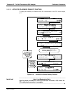
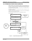
10.3.1. ZERO/SPAN CHECK PROCEDURES
The Zero and Span calibration can be checked a variety of ways. They include:
Manual Zero/Span Check - Zero and Span can be checked via the front panel
control buttons. Please refer to Sections 9.3 and 9.6 of this manual.
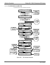
Automatic Zero/Span Checks - Af
ter the appropriate setup, Z/S checks can be
performed automatically every night. Refer to Section 9.8 of this manual for setup
and operation
procedures.
Ze
ro/Span checks via remote contact closure - Zero/Span checks can be initiated
via remote contact closures on the rear panel. Refer to Section 9.7.1 of this manual.
Z
e
ro/Span via RS-232 port - Z/S checks can be controlled via the RS-232 port.
Refer to Section 8 and Appendix A-6 of this manual for more details.
10.4. PRECISION CALIBRATION PROCEDURES AND CHECKS
Calibration must be performed with a calibrator that meets all conditions specified in
Subsection 2.9.2 (Q.A. Handbook). The user should be sure that all flow meters are
calibrated under the conditions of use against a reliable standard. All volumetric flow
rates should be corrected to 25
o
C (77
o
F) and 760mm (29.92in) Hg. Ensure that the
calibration system can supply the range of the concentration at a sufficient flow over the
whole range of concentration that will be encountered during calibration.
All operational adjustments to the T100 should be completed prior to calibration. The
following software features must be set to the desired state before calibration.
06807C DCN6650