


Principles of Operation Teledyne API - T100 UV Fluorescence SO2 Analyzer
292
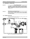
13.3.2. CO
2
OPERATION WITHIN THE T100 ANALYZER
The CO2 sensor option is transparently integrated into the core analyzer operation. All
functions can be viewed or accessed through the front panel display, just like the
functions for SO
2
.
The CO
2
concentration is displayed below the SO
2
concentration.
Test functions for CO
2
slope and offset are viewable from the front panel along with
the other test functions of the analyzer.
CO
2
sensor calibration is performed via the front panel CAL function and is
performed in a nearly identical manner as the standard SO
2
calibration.
Stability of the CO
2
sensor can be viewed via the front panel (refer to Section
9.10.2.3).
Refer to Section 3.4.4.
3 for information on calibrating the CO
2
.
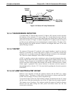
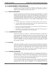
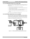
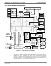
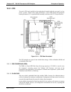
13.3.3. ELECTRONIC OPERATION OF THE CO
2
SENSOR
The CO
2
PCA, which is mounted to the rear side of the Relay Board Mounting Bracket,
controls the CO
2
sensor. It converts the sensor’s digital output to an analog voltage that
is measured with the motherboard and draws 12 VDC from the analyzer via the relay
card from which converts to fit the power needs of the probe and its own onboard logic.
It outputs a 0-5 VDC analog signal to the analyzer’s CPU via the motherboard that
corresponds to the concentration of CO
2
measured by the probe.
CPU
Analog
Output
To CO
2
Probe
OVDC 5VDC
GND +12 V
Power Supply
Connections
LED V8 LED V9
Serial I/O
(Not Used)
Purple wire
22 awg
Orange wire
22 awg
Relay PCA
J12
Pin 7
Pin 8
Pin 2
Pin 8
Motherboard
P110
Grey wire
22 awg
Black wire
22 awg
Figure 13-9: CO2 Sensor Option PCA Layout and Electronic Connections
06807C DCN6650