


Introduction, Features and Options Teledyne API - T100 UV Fluorescence SO2 Analyzer
26
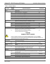
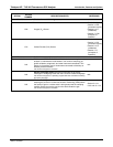
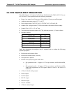
OPTION
OPTION
NUMBER
DESCRIPTION/NOTES REFERENCE
Calibration Valves
Used to control the flow of calibration gases generated from external sources, rather
than manually switching the rear panel pneumatic connections.
50A
Two Teflon® solenoid valve sets located inside the analyzer:
Zero/Span valve switches between zero air and span gas;
Sample/Cal valve switches between sample gas and calibration gas.
Sections 3.3.2.3,
3.3.2.4, 9.4, 9.5
and 9.6
Internal Zero/Span (IZS)
Gas Generator
Generates internal zero air and span gas.
51A
Includes heated enclosure for a permeation tube (tube not included –
see SO
2
IZS Permeation Tubes options), an external scrubber for
producing zero air and a set of valves for switching between the
sample gas inlet and the output of the zero/span subsystem,
functionally very similar to the valves included in the zero/span valve
option.
Sections 3.3.2.4,
9.5, 11.3.2 and
12.6.17
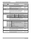
SO
2
IZS Permeation Tubes Replacement tubes for the IZS option; identical size/shape; different effusion rates.
Effusion Rate (@ 50°C)
Approximate
Concentration
Specified Flow Rate (of
indicated perm tube rate)
52C 796 ng/min 0.3-0.5 ppm 0.76 ± 5% lpm N/A
52H 1592 ng/min 0.8 ppm 0.76 ± 50% lpm N/A
52M 220 ng/min 150 ppb 0.56 ± 25% lpm N/A
Each tube comes with a calibration certificate, traceable to a NIST
standard, specifying its actual effusion rate of that tube to within ± 5%
when immersed in a gas stream moving at the specified flow rate. This
calibration is performed at a tube temperature of 50°C.
Sections 3.3.2.4,
9.1.1.3 and 10.1.4
Communication Cables For remote serial, network and Internet communication with the analyzer.
Type Description
60A RS-232
Shielded, straight-through DB-9F to DB-25M cable, about
1.8 m long. Used to interface with older computers or code
activated switches with DB-25 serial connectors.
Section 3.3.1.8
and 6.3
60B RS-232
Shielded, straight-through DB-9F to DB-9F cable of about
1.8 m length.
Sections 3.3.1.8,
and 6.3, and 7.2.7
60C Ethernet
Patch cable, 2 meters long, used for Internet and LAN
communications.
Sections 3.3.1.8
and 6.5
60D USB
Cable for direct connection between instrument (rear panel
USB port) and personal computer.
Sections3.3.1.8
and 6.5.1
Concentration Alarm
Relay
Issues warning when gas concentration exceeds limits set by user.
61
Four (4) “dry contact” relays on the rear panel of the instrument. This
relay option is different from and in addition to the “Contact Closures”
that come standard on all TAPI instruments.
Sections 3.3.1.7
and 3.4.4
RS-232 Multidrop Enables communications between host computer and up to eight analyzers.
62
Multidrop card seated on the analyzer’s CPU card.
Each instrument in the multidrop network requires this card and a
communications cable (Option 60B).
Section 3.3.1.8
06807C DCN6650