


Teledyne API - T100 UV Fluorescence SO2 Analyzer Principles of Operation
293
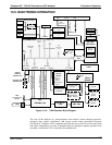
13.4. PNEUMATIC OPERATION
IMPORTANT
IMPACT ON READINGS OR DATA
It is important that the sample airflow system is leak-tight and not
pressurized over ambient pressure. Regular leak checks should be
performed on the analyzer as described in the maintenance schedule,
Table 11-1. Procedures for correctly performing leak checks can be found
in Section 11.3.6.
IMPORTANT
Relative Pressure versus Absolute Pressure
In this manual vacuum readings are given in inches of mercury absolute
pressure (in-Hg-A), i.e. indicate an absolute pressure referenced against
zero (a perfect vacuum).
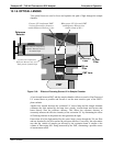
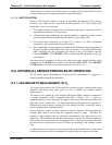
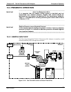
13.4.1. SAMPLE GAS FLOW
The Flow of gas through the T100 UV Fluorescence SO
2
Analyzer is created by a small
internal pump that pulls air though the instrument.
VACUUM MANIFOLD
FLOW
CONTROL
ASSY
EXHAUST TO OUTER
LAYER OF KICKER
SAMPLE
gas inlet
SAMPLE FILTER
Chassis
EXHAUST
gas outlet
KICKER EXHAUST
TO PUMP
HYDROCARBON
SCRUBBER
(KICKER)
UV
LAMP
PMT
SAMPLE
CHAMBER
FLOW
SENSOR
FLOW / PRESSURE
SENSOR PCA
SAMPLE
PRESSURE
SENSOR
PUMP
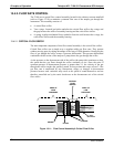
CRITICAL
FLOW
ORIFICE
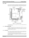
Figure 13-10: Gas Flow and Location of Critical Flow Orifice
06807C DCN6650