


SETUP Menu Teledyne API - T100 UV Fluorescence SO2 Analyzer
122
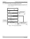
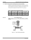
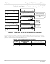
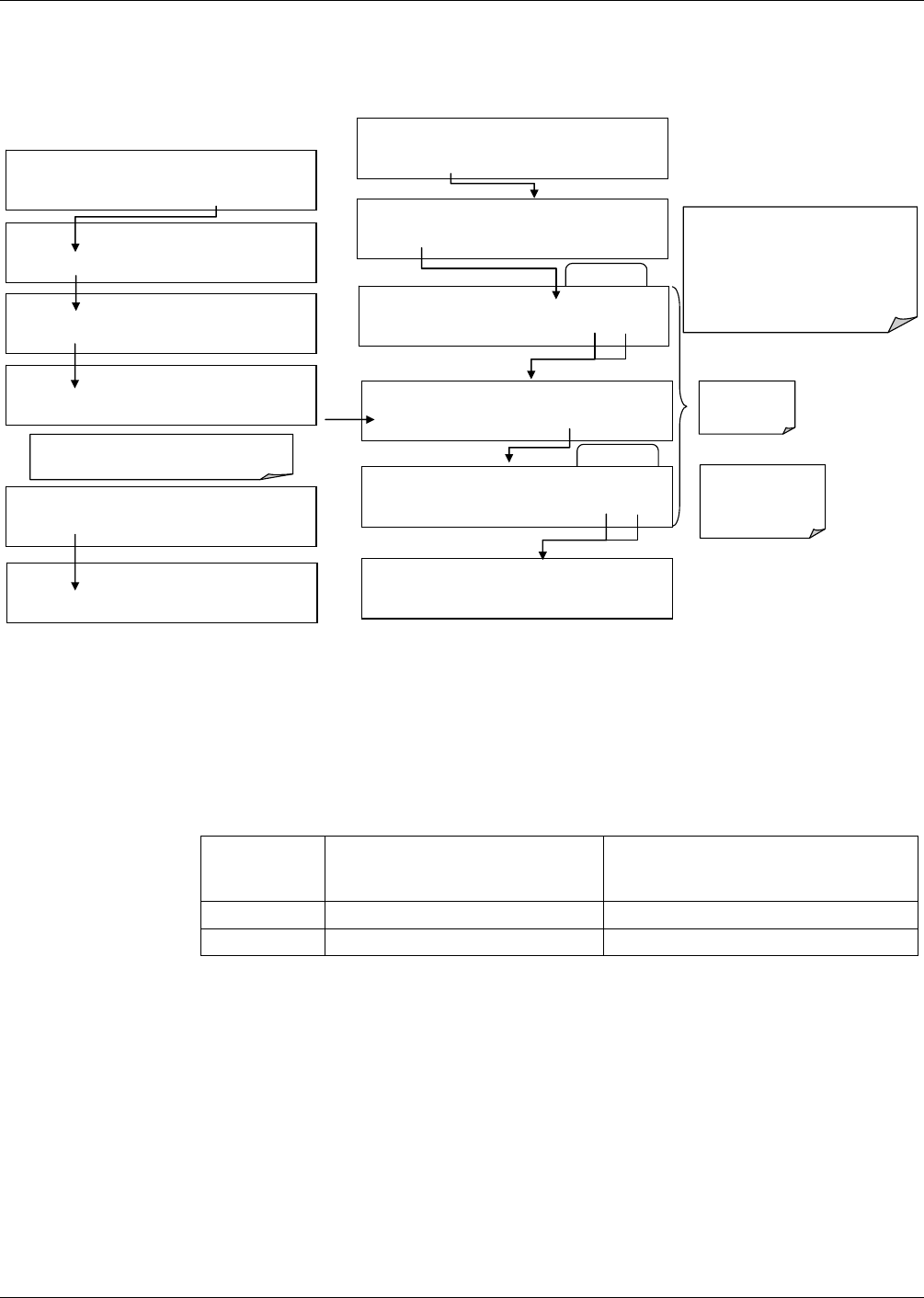
To adjust the zero and span values of the current outputs, activate the ANALOG I/O
CONFIGURATION MENU from the DIAG Menu (refer to Figure 5-16), then press:
EXAMPLE
DIAG ANALOG I / O CONFIGURATION
PREV NEXT ENTR EXIT
DIAG AIO AIN A/C FREQUENCY: 60 HZ
SET> EDIT EXIT
DIAG AIO AOUT CALIBRATED: NO
< SET SET> CAL EXIT
DIAG AIO CONC_OUT_2 RANGE: CURR
<SET SET> EDIT EXIT
DIAG AIO CONC_OUT_2 CALIBRATED: NO
< SET CAL EXIT
DIAG AIO CONC_OUT_2 ZERO: 0 mV
U100 UP10 UP DOWN DN10 D100 ENTR EXIT
DIAG AIO CONC_OUT_CURR, NO CAL
< SET SET> EDIT EXIT
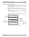
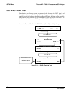
Press SET> to select the analog output channel
to be configured:. Then press EDIT to continue
DIAG AIO AIN CALIBRATED: NO
SET> EDIT EXIT
ENTR
r
eturns
to the previous
menu.
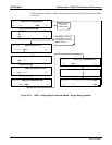
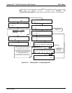
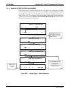
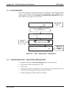
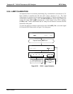
Increase or decrease the current
output by 100, 10 or 1 counts. The
resulting change in output voltage is
displayed in the upper line.
Continue adjustments until the correct
current is measured with the current
meter.
DIAG AIO CONC_OUT_2 ZERO: 27 mV
U100 UP10 UP DOWN DN10 D100 ENTR EXIT
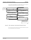
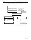
EXIT ignores the
new setting, ENTR
accepts the new
setting.
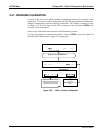
DIAG AIO CONC_OUT_2 CALIBRATED: YES
< SET CAL EXIT
DIAG AIO CONC_OUT_2 SPAN: 10000 mV
U100 UP10 UP DOWN DN10 D100 ENTR EXIT
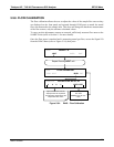
EXAMPLE
DIAG AIO CONC_OUT_2 ZERO: 9731 mV
U100 UP10 UP DOWN DN10 D100 ENTR EXIT
Figure 5-27: Analog Output – Zero and Span Value Adjustment for Current Outputs
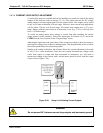
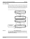
If a current meter is not available, an alternative method for calibrating the current loop outputs is to connect a
250 1% resistor across the current loop output. Using a voltmeter, connected across the resistor, follow the
procedure above but adjust the output to the following values:
Table 5-8: Current Loop Output Calibration with Resistor
FULL SCALE
VOLTAGE FOR 2-20 MA
(MEASURED ACROSS
RESISTOR)
VOLTAGE FOR 4-20 MA
(MEASURED ACROSS RESISTOR)
0% 0.5 V 1.0 V
100% 5.0 V 5.0 V
06807C DCN6650