


Teledyne API - T100 UV Fluorescence SO2 Analyzer Getting Started
63
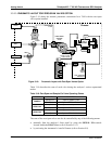
remotely by using the external digital control inputs (refer to Section 8.1.2 and
Section 9.7.1)
remo
tely through the RS-232/485 serial I/O ports (refer to Appendix A-6 for the
appropriate commands)
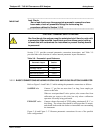
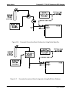
Sources of zero and span gas must be capable of supplying at least 1.55 L/min.
(maximum 2.5L/min). Both supply lines should be vented outside of the analyzer’s
enclosure. In order to prevent back-diffusion and pressure effects, these vent lines
should be between 2 and 10 meters in length.
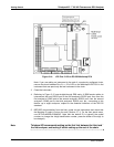
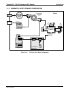
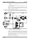
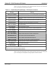
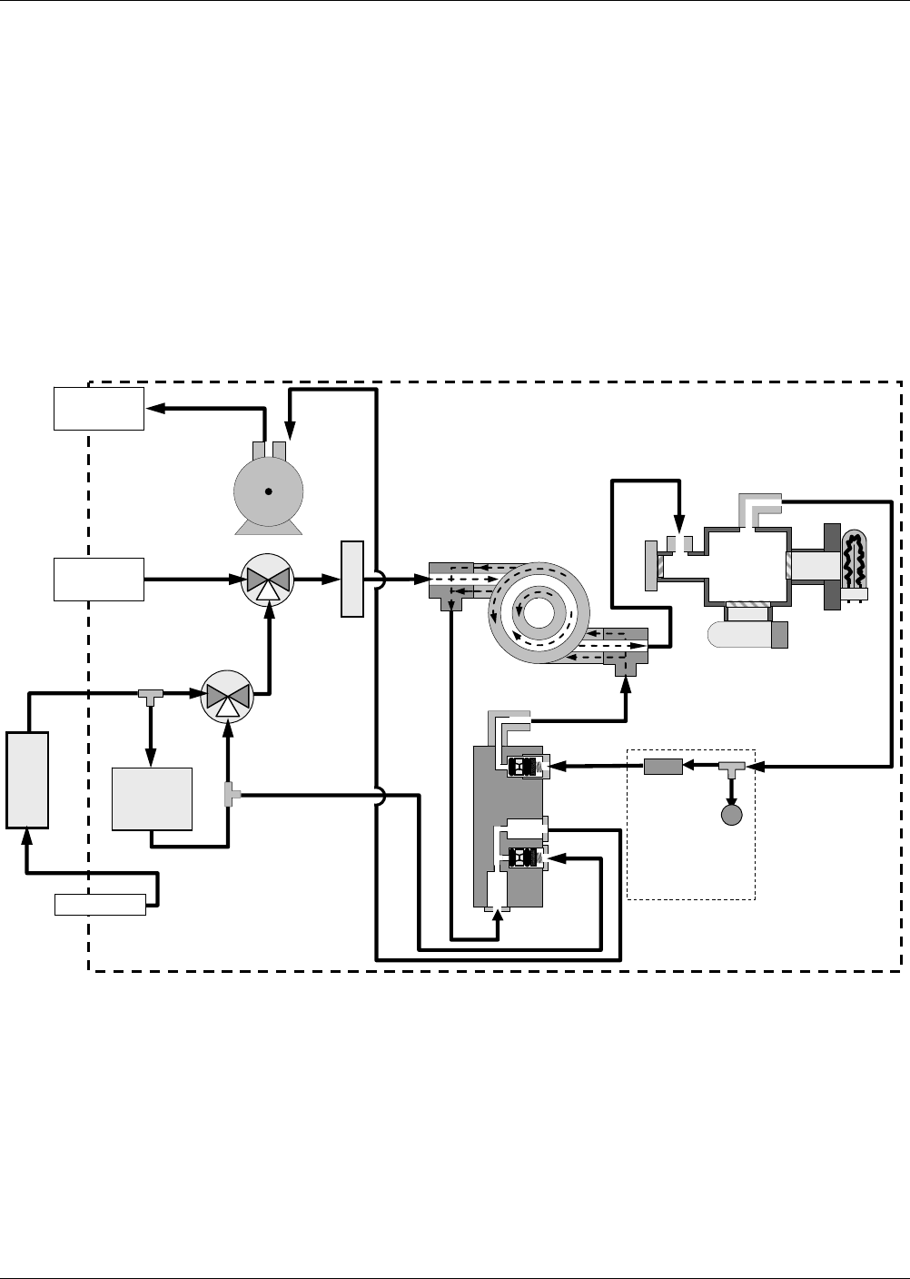
3.3.2.4. PNEUMATIC LAYOUT FOR INTERNAL ZERO/SPAN (IZS) GAS GENERATOR OPTION
Figure 3-20 shows the internal, pneumatic connecti
ons for the analy
zer with the IZS
option installed.
EXHAUST TO OUTER LA
Y
E
R
OF KICKER
VACUUM MANIFOLD
CRITICAL
FLOW
ORIFICE
CRITICAL
FLOW
ORIFICE
ZERO AIR
SCRUBBER
SAMPLE/CAL
VALVE
Chassis
EXHAUST GAS
OUTLET
SAMPLE GAS
INLET
KICKER EXHAUST
TO PUMP
HYDROCARBON
SCRUBBER
(KICKER)
ZERO AIR INLET
UV
LAMP
PMT
SAMPLE
CHAMBER
FLOW
SENSOR
FLOW / PRESSURE
SENSOR PCA
SAMPLE
PRESSURE
SENSOR
PUMP
IZS
Permeation
Tube
SO
2
Source
ZERO/SPAN
VALVE
SAMPLE FILTER
NC
NO
COM
NC
NO
COM
Figure 3-20: Pneumatic Layout with IZS Options
The internal zero air and span gas generator (IZS) option includes a heated enclosure
(Section 3.3.2.5) for a permeation tube (permeation tube
must be purchased separately;
see Section 1.4, in SO
2
IZS Permeation Tubes option), an external scrubber (Section
3.3.2.7) for producing zero air and a set of valves for switching between the sample gas
inlet and the output of the
zero/span subsystem, functionally very similar to the valves
included in the zero/span valve option.
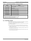
Table 3-11 describes the operational state of the valves associate
d with the IZS option
during the analyzer’s various operating modes.
06807C DCN6650