


Principles of Operation Teledyne API - T100 UV Fluorescence SO2 Analyzer
296
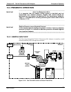
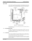
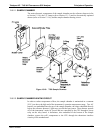
13.4.4. PNEUMATIC SENSORS
The T100 uses two pneumatic sensors to verify gas streams. These sensors are located
on a printed circuit assembly, called the pneumatic pressure/flow sensor board. The flow
simultaneously enters the sample pressure sensor and the flow sensor from the outlet of
the reaction cell.
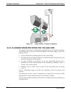
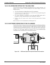
13.4.4.1. SAMPLE PRESSURE SENSOR
An absolute pressure transducer plumbed to the input of the analyzer’s sample chamber
is used to measure the pressure of the sample gas before it enters the chamber. This
upstream used to validate the critical flow condition (2:1 pressure ratio) through the
instrument’s critical flow orifice (refer to Section 13.4.2). Also, if the
Tem
perature/Pressure Compensation (TPC) feature is turned on (refer to Section
13.7.3), the output of this sensor is also used to supply pressure data for that calculation.
The actual pressure
measurement is viewable through the analyzer’s front panel display
as the test function PRESS.
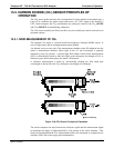
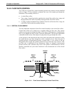
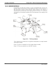
13.4.4.2. SAMPLE FLOW SENSOR
A thermal-mass flow sensor is used to measure the sample flow through the analyzer.
This sensor is also mounted on the pneumatic pressure/flow sensor board upstream of
the sample chamber. The flow rate is monitored by the CRT which issues a warning
message (SAMP FLOW WARN) if the flow rate is too high or too low.
The flow rate of the sample gas is viewable via the front panel as the SAMP FL test
function.
06807C DCN6650