


SETUP Menu Teledyne API - T100 UV Fluorescence SO2 Analyzer
118
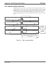
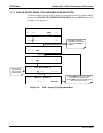
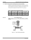
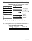
5.9.3.3. MANUAL ANALOG OUTPUT CALIBRATION AND VOLTAGE ADJUSTMENT
For highest accuracy, the voltages of the analog outputs can be manually calibrated.
Calibration is done through the instrument software with a voltmeter connected across
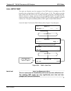
the output terminals (refer to Figure 5-23). Adjustments are made using the control
buttons
b
y setting the zero-point first and then the span-point (refer to Table 5-7).
The software allows this adjustment to b
e made in 100, 10 or 1 count increments.
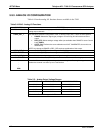
Table 5-7: Voltage Tolerances for Analog Output Calibration
FULL SCALE ZERO TOLERANCE SPAN VOLTAGE SPAN TOLERANCE
0.1 VDC ±0.0005V 90 mV ±0.001V
1 VDC ±0.001V 900 mV ±0.001V
5 VDC ±0.002V 4500 mV ±0.003V
10 VDC ±0.004V 4500 mV ±0.006V
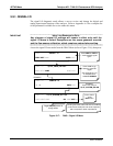
IMPORTANT
IMPACT ON READINGS OR DATA
Outputs configured for 0.1V full scale should always be calibrated
manually.
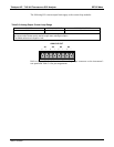
V
+DC Gnd
V OUT +
V OUT -
V IN +
V IN -
Recording
Device
ANALYZER
See Table 3-1 for
pin assignments
of Analog Out
connector on the
rear panel
Figure 5-23: Setup for Calibrating Analog Outputs
06807C DCN6650