


Troubleshooting & Service Teledyne API - T100 UV Fluorescence SO2 Analyzer
256
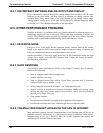
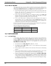
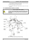
Figure 12-5: Manual Activation of the UV Light Shutter
12.6.11. PMT SENSOR
The photo multiplier tube detects the light emitted by the UV excited fluorescence of
SO
2
. It has a gain of about 500000 to 1000000. It is not possible to test the detector
outside of the instrument in the field. The best way to determine if the PMT is working
properly is by using the optical test (OTEST), which is described in Section 5.9.4. The
basic method
to diagnose a PMT fault is to eliminate the other components using
ETEST, OTEST and specific tests for other sub-assemblies.
12.6.12. PMT PREAMPLIFIER BOARD
To check the correct operation of the preamplifier board, we suggest the technician carry
out the electrical and optical tests described in 5.9.4 and 5.9.5.
If the ETEST
fails, the preamplifier board may be faulty.
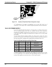
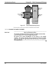
12.6.13. PMT TEMPERATURE CONTROL PCA
The TEC control printed circuit assembly is located on the sensor housing assembly,
under the slanted shroud, next to the cooling fins and directly above the cooling fan.
If the red LED located on the top edge of this assembly is not glowing the control
circuit is not receiving power.
Check the analyzer's power supply, the relay board’s power distribution circuitry
and the wiring connecting them to the PMT temperature control PCA.
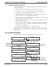
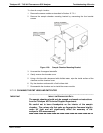
12.6.13.1. TEC CONTROL TEST POINTS
Four test points are also located at the top of this assembly they are numbered left to
right start with the T1 point immediately to the right of the power status LED. These
test points provide information regarding the functioning of the control circuit.
To determine the current running through the control circuit, measure the voltage
between T1 and T2. Multiply that voltage by 10.
To determine the drive voltage being supplied by the control circuit to the TEC, measure
the voltage between T2 and T3.
If this voltage is zero, the TEC circuitry is most likely open.
If the voltage between T2 and T3 = 0 VDC and the voltage measured between T1
and T2 = 0 VDC there is most likely an open circuit or failed op amp on control
PCA itself
If the voltage between T2 and T3 = 0 VDC and the voltage measured between T1 to
T2 is some voltage other than 0 VDC, the TEC is most likely shorted
T4 is tied directly to ground. To determine the absolute voltage on any one of the other
test points make a measurement between that test point and T4.
12.6.14. HIGH VOLTAGE POWER SUPPLY
The HVPS is located in the interior of the sensor module and is plugged into the PMT
tube (refer to Figure 13-17). It requires 2 voltage inputs. The first is +15 which powers
06807C DCN6650