


Teledyne API - T100 UV Fluorescence SO2 Analyzer Principles of Operation
287
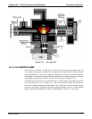
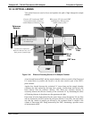
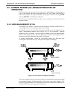
13.1.8. OPTICAL LENSES
Two optical lenses are used to focus and optimize the path of light through the sample
chamber.
214 nm
Filter
330 nm
Filter
UV Source
Lens
PMT Lens
Reference
Detector
If source UV is unfocused, PMT
receives fluorescence from area
outside Reference Detector’s view
PMT
When source UV is focused, PMT
and Reference Detector view
similar volume of SO
2
*
When source UV is focused,
Reference Detector most of
the emitted light
If source UV is unfocused,
Reference Detector only sees a
small portion of emitted light
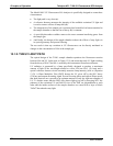
Figure 13-6: Effects of Focusing Source UV in Sample Chamber
A lens located between PMT and the sample chamber collects as much of the fluoresced
UV created there as possible and focuses it on the most sensitive part of the PMT’s
photo cathode.
Another lens located between the excitation UV source lamp and the sample chamber
collimates the light emitted by the lamp into a steady, circular beam and focuses that
beam directly onto the reference detector. This allows the reference detector to
accurately measure the effective intensity of the excitation UV by eliminating the effect
of flickering inherent in the plasma arc that generates the light.
Ensure that all of the light emitted by the source lamp, passes though the 214 nm filter
and not absorbed by the SO
2
reaches the reference detector. Conversely, this also makes
sure that the volume of sample gas affected by the excitation beam is similar to the
volume of fluorescing SO
2
* being measured by the PMT, eliminating a possible source
of measurement offset.
06807C DCN6650