


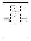

175
8. REMOTE OPERATION OF THE ANALYZER
This section provides information needed when using external digital and serial I/O and
when using Hessen protocol for remote operation. It also provides references to
communications-related manuals.
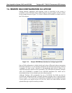
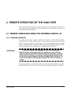
8.1. REMOTE OPERATION USING THE EXTERNAL DIGITAL I/O
8.1.1. STATUS OUTPUTS
The status outputs report analyzer conditions via optically isolated NPN transistors,
which sink up to 50 mA of DC current. These outputs can be used interface with
devices that accept logic-level digital inputs, such as programmable logic controllers
(PLC’s). Each Status bit is an open collector output that can withstand up to 40 VDC.
All of the emitters of these transistors are tied together and available at D.
ATTENTION
COULD DAMAGE INSTRUMENT AND VOID WARRANTY
Most PLC’s have internal provisions for limiting the current that the
input will draw from an external device. When connecting to a unit that
does not have this feature, an external dropping resistor must be used
to limit the current through the transistor output to less than 50 mA. At
50 mA, the transistor will drop approximately 1.2V from its collector to
emitter.
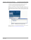
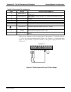
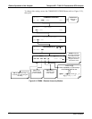
The status outputs are accessed through a 12 pin connector on the analyzer’s rear panel
labeled STATUS (refer to Figure 3-4). The function of each pin is defined in Table 8-1.
06807C DCN6650