


Teledyne API - T100 UV Fluorescence SO2 Analyzer Troubleshooting & Service
273
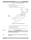
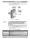
10. Change the PMT or the HVPS or both, clean the PMT glass tube with a clean, anti-
static wipe and DO NOT TOUCH it after cleaning.
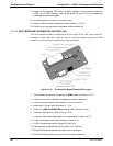
11. If the cold block or TEC is to be changed disconnect the TEC driver board from the
preamplifier board.
Remove the cooler fan duct (4 screws on its side) including the driver board.
Disconnect the driver board from the TEC and set the sub-assembly aside.
Remove the end plate with the cooling fins (4 screws) and slide out the PMT cold
block assembly, which contains the TEC.
Unscrew the TEC from the cooling fins and the cold block and replace it with a new
unit.
12. Re-assemble the TEC subassembly in reverse order.
ATTENTION
COULD DAMAGE INSTRUMENT AND VOID WARRANTY
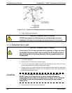
The thermo-electric cooler needs to be mounted flat to the heat sink. If
there is any significant gap, the TEC might burn out. Ensure to apply heat
sink paste before mounting it and tighten the screws evenly and cross-
wise.
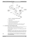
Ensure to use thermal grease between TEC and cooling fins as well as between TEC
and cold block.
Align the side opening in the cold block with the hole in the PMT housing where the
sample Chamber attaches.
Evenly tighten the long mounting screws for good thermal conductivity.
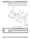
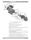
13. Re-insert the TEC subassembly. Ensure that the O-ring is placed properly and the
assembly is tightened evenly.
14. Re-insert the PMT/HVPS subassembly.
Don’t forget the gasket between HVPS and PMT.
Use new plastic screws to mount the PMT assembly on the PMT cold block.
15. Insert the LED and thermistor into the cold block.
16. Replace the desiccant bags with five new desiccant bags.
17. Carefully replace the end plate.
Ensure that the O-ring is properly in place. Improperly placed O-rings will cause
leaks, which – in turn – cause moisture to condense on the inside of the cooler
causing the HVPS to short out.
18. Reconnect the cables and the reaction cell
Be sure to tighten these screws evenly.
19. Replace the sensor assembly into the chassis and fasten with four screws and
washers.
20. Perform a leak check the system.
06807C DCN6650