


Getting Started Teledyne API - T100 UV Fluorescence SO2 Analyzer
44
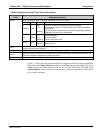
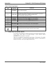
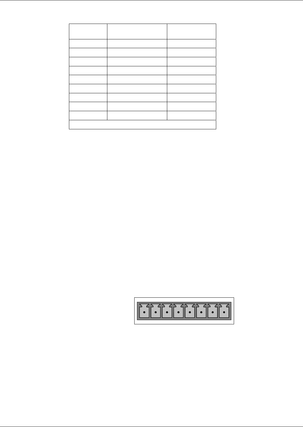
Table 3-5: Analog Input Pin Assignments
PIN DESCRIPTION
DAS
PARAMETER
1
1 Analog input # 1 AIN 1
2 Analog input # 2 AIN 2
3 Analog input # 3 AIN 3
4 Analog input # 4 AIN 4
5 Analog input # 5 AIN 5
6 Analog input # 6 AIN 6
7 Analog input # 7 AIN 7
8 Analog input # 8 AIN 8
GND Analog input Ground N/A
1
See Section 0 for details on setting up the DAS.
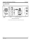
3.3.1.3. CONNECTING ANALOG OUTPUTS
The T100 is equipped with several analog output channels accessible through a
connector on the rear panel of the instrument. The standard configuration for these
outputs is mVDC. An optional current loop output is available for each. (Section
3.3.1.4).
When the instrument is in its default co
nfiguration, channels A1 and A2 output a signal
that is proportional to the SO
2
concentration of the sample gas. Either can be used for
connecting the analog output signal to a chart recorder or for interfacing with a
datalogger.
Output A3 is only used on the T100 if the optional O
2
or CO
2
sensor is installed.
Channel A4 is special. It can be set by the user (refer to Section 5.9.9) to output any
one of th
e parameters accessible through the <TST TST> buttons of the unit’s sample
display.
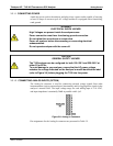
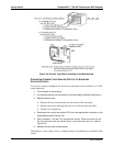
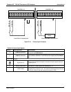
To access these signals attach a strip chart recorder and/or data-logger to the appropriate
analog output connections on the rear panel of the analyzer.
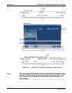
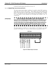
A
NALOG OUT
A1
A
2 A3 A4
+ - + - + - + -
Figure 3-7: Analog Output Connector
06807C DCN6650