


Teledyne API - T100 UV Fluorescence SO2 Analyzer Getting Started
51
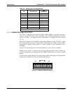
The software for this instrument is flexible enough to allow you to configure the alarms
so that you can have two alarm levels for each concentration.
SO
2
Alarm 1 = 20 PPM
SO
2
Alarm 2 = 100 PPM
SO
2
Alarm 1 = 20 PPM
SO
2
Alarm 2 = 100 PPM
In this example, SO
2
Alarm 1 and SO
2
Alarm 1 will both be associated with the “Alarm
2” relay on the rear panel. This allows you to have multiple alarm levels for individual
concentrations.
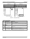
A more likely configuration for this would be to put one concentration on the “Alarm 1”
relay and the other concentration on the “Alarm 2” relay.
SO
2
Alarm 1 = 20 PPM
SO
2
Alarm 2 = Disabled
SO
2
Alarm 1 = Disabled
SO
2
Alarm 2 = 100 PPM
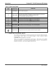
“ALARM 4” RELAY
This relay is connected to the “range bit”. If the instrument is configured for “Auto
Range” and the reading goes up into the high range, it will turn this relay on.
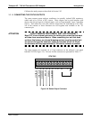
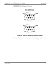
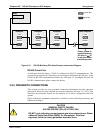
3.3.1.8. CONNECTING THE COMMUNICATIONS INTERFACES
The T-Series analyzers are equipped with connectors for remote communications
interfaces: Ethernet, USB, RS-232, RS-232 Multidrop and RS-485. In addition to
using the appropriate cables, each type of communication method, must be configured
using the SETUP>COMM menu, Section 6. Although Ethernet is DHCP-enabled by
default, it can also be configured ma
nually (Section 6.5.1) to set up a static IP address,
which is the recommended setting when operating the
instrument via Ethernet.
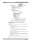
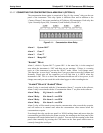
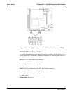
ETHERNET CONNECTION
For network or Internet communication with the analyzer, connect an Ethernet cable
from the analyzer’s rear panel Ethernet interface connector to an Ethernet port. Please
refer to Section 6.5 for a description of the default configuration and setup instructions.
Configuration: Section 6.5
manual configuration: Section 6.5.1
automatic configuration (default): Secti
on 6.5.2
06807C DCN6650