


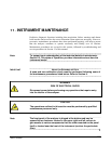

Instrument Maintenance Teledyne API - T100 UV Fluorescence SO2 Analyzer
230
Appendix B) comes with a Material and Safety Data Sheet, which contains more
information on these chemicals.
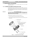
5. Refill the scrubber with charcoal at the bottom.
6. Tighten the cap on the scrubber - hand-tight only.
7. Replace the DFU filter, if required, with a new unit and discard the old.
8. Replace the scrubber assembly into its clips on the rear panel.
9. Reconnect the plastic tubing to the fitting of the particle filter.
10. Adjust the scrubber cartridge such that it does not protrude above or below the
analyzer in case the instrument is mounted in a rack. If necessary, squeeze the clips
for a tighter grip on the cartridge.
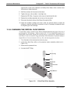
11.3.4. CHANGING THE CRITICAL FLOW ORIFICE
A critical flow orifice, located on the exhaust manifold maintains the proper flow rate of
gas through the T100 analyzer. Refer to section 10.3.2.1 for a detailed description of its
functionality and location. Despite the fact this device is protected by sintered stainless
steel filters, it can, on occasion, clog, particularly if the instrument is operated without a
sample filter or in an environment with very fine, sub-micron particle-size dust.
1. Turn off power to the instrument and vacuum pump.
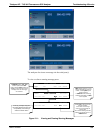
2. Locate the critical flow orifice on the pressure sensor assembly (called out in
Figure 11-2).
3.
Disco
nnect the pneumatic line.
4. Unscrew the NPT fitting.
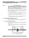
Gas Line fitting
Spring
Sintered Filter
O-Ring
Critical Flow Orifice
O-Ring
Vacuum Manifold
Figure 11-2: Critical Flow Orifice Assembly
06807C DCN6650