


Teledyne API - Models T100, 100E Series (05036F DCN6650) APPENDIX A - Version Specific Software Documentation
Rev 1.0.3 (T-Series)/G6 (E-Series)
A-37
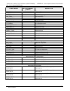
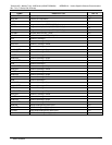
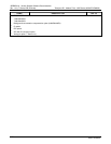
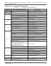
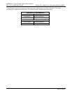
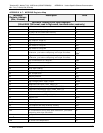
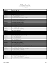
APPENDIX A-7: MODBUS Register Map
MODBUS
Register Address
(dec., 0-based)
Description Units
MODBUS Floating Point Input Registers
(32-bit IEEE 754 format; read in high-word, low-word order; read-only)
0 PMT detector reading mV
2 UV lamp intensity reading mV
4 UV lamp ratio of calibrated intensity %
6 PMT electrical offset mV
8 UV lamp electrical offset mV
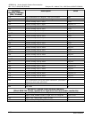
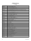
10 SO
2
slope for range #1 —
12 SO
2
slope for range #2 —
14 SO
2
offset for range #1 mV
16 SO
2
offset for range #2 mV
18 SO
2
concentration for range #1 during zero/span
calibration, just before computing new slope and offset
PPB,
PPM
2
20 SO
2
concentration for range #2 during zero/span
calibration, just before computing new slope and offset
PPB
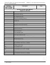
22 SO
2
concentration for range #1 PPB
24 SO
2
concentration for range #2 PPB
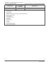
26 Concentration stability PPB
28 Stray light reading PPB
30 Reaction cell temperature C
32 PMT temperature C
34 Sample pressure “Hg
36 Internal box temperature C
38 High voltage power supply output Volts
40 Diagnostic test input (TEST_INPUT_8) mV
42 Diagnostic temperature input (TEMP_INPUT_5) C
44 Diagnostic temperature input (TEMP_INPUT_6) C
46 Ground reference (REF_GND) mV
48 4096 mV reference (REF_4096_MV) mV
50 Sample flow cc/m
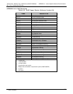
52
1
IZS temperature C
54
2
Vacuum pressure “Hg
56
1
Pre-amplified UV lamp intensity reading mV
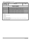
100
10
O
2
concentration %
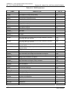
102
10
O
2
concentration during zero/span calibration, just before
computing new slope and offset
%
104
10
O
2
slope —
106
10
O
2
offset %
108
10
O
2
sensor cell temperature C
06807C DCN6650