


Troubleshooting & Service Teledyne API - T100 UV Fluorescence SO2 Analyzer
244
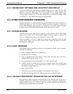
12.2.3. RELAY BOARD STATUS LEDS
The most important status LED on the relay board is the red I
2
C Bus watch-dog LED,
labeled D1 (or W/D), which indicates the health of the I
2
C communications bus. This
LED is located in the upper left-hand corner of the relay board when looking at the
electronic components. If D1 is blinking, then the other LEDs can be used in
conjunction with the DIAG menu I/O functions to test hardware functionality by
switching devices on and off and watching the corresponding LED turn on or off. The
LED only indicates that the logic signal for an output has been activated. If the output
driver (i.e. the relay or valve driver IC) is defective, then the LED will light up, but the
attached peripheral device will not turn on.
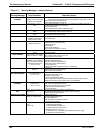
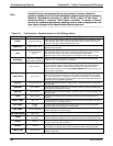
Table 12-3: Relay Board Status LEDs
LED COLOR FUNCTION
FAULT
STATUS
INDICATED FAILURE(S)
D1 red
Watchdog Circuit; I
2
C
bus operation.
Continuously
ON or OFF
Failed/Halted CPU
Faulty Mother Board, Valve Driver board or
Relay PCA
Faulty Connectors/Wiring between Motherboard,
Valve Driver board or Relay PCA
Failed/Faulty +5 VDC Power Supply (PS1)
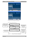
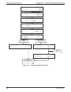
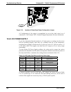
12.3. GAS FLOW PROBLEMS
The standard analyzer has one main flow path. With the IZS option installed, there is a
second flow path through the IZS oven that runs whenever the IZS is on standby to
purge SO
2
from the oven chamber. The IZS flow is not measured so there is no reading
for it on the front panel display. The full flow diagrams of the standard configuration
(refer to Figure 3-18) and with options installed (refer to Figure 3-19 and Figure 3-20)
help in trou
bleshooting flow problems. In general, flow problems can be divided into
three categories:
Flow is too high
Flow is greater than zero, but is too low, and/or unstable
Flow is zero (no flow)
When troubleshooting flow problems, it is essential to confirm the actual flow rate
without relying on the analyzer’s flow display. The use of an independent, external flow
meter to perform a flow check as described in Section 12.5.2 is essential.
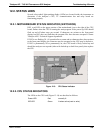
12.3.1. ZERO OR LOW SAMPLE FLOW
If the pump is operating but the unit reports a XXXX gas flow, do the following three
steps:
Check for actual sample flow
Check pressures
Carry out a leak check
To check the actual sample flow, disconnect the sample tube from the sample inlet on
the rear panel of the instrument. Ensure that the unit is in basic SAMPLE mode. Place a
06807C DCN6650