


Teledyne API - T100 UV Fluorescence SO2 Analyzer Troubleshooting & Service
249
If neither of the Ethernet cable’s two status LED’s (located on the back of the cable
connector) is lit while the instrument is connected to a network:
Verify that the instrument is being connected to an active network jack.
Check the internal cable connection between the Ethernet card and the CPU board.
12.6. SUBSYSTEM CHECKOUT
The preceding sections of this manual discussed a variety of methods for identifying
possible sources of failures or performance problems within the analyzer. In most cases
this included a list of possible causes and, in some cases, quick solutions or at least a
pointer to the appropriate sections describing them. This section describes how to
determine if a certain component or subsystem is actually the cause of the problem being
investigated.
12.6.1. AC POWER CONFIGURATION
The T100 digital electronic systems will operate with any of the specified power
regimes. As long as instrument is connected to 100-120 VAC or 220-240 VAC at either
50 or 60 Hz it will turn on and after about 30 seconds show a front panel display.
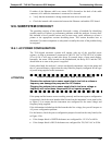
Internally, the status LEDs located on the Motherboard, the Relay PCA and the CPU
should turn on as soon as the power is supplied.
On the other hand, the analyzer’s various non-digital components, such as the pump and
the AC powered heaters, require that the relay board be properly configured for the type
of power being supplied to the instrument.
ATTENTION
COULD DAMAGE INSTRUMENT AND VOID WARRANTY
Plugging the analyzer into a power supply that is too high a voltage or
frequency can damage the pump and the AC Heaters.
Plugging the analyzer into a power supply that is too low a voltage or
frequency will cause these components to not operate properly.
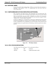
If the pump and the heaters are not working correctly and incorrect power configuration
is suspected, check the serial number label located on the instrument’s rear panel (refer
to Figure 3-4) to ensure that the instrument was
configured for the same voltage and
frequency being supplied.
If the information included on the label matches the line voltage, but you still suspect an
AC power configuration problem:
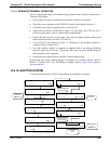
For the heaters, check the power configuration jumpers located on the relay board (refer
to Figure 12-4).
If the Jump
er block is WHITE the heaters are configured for 115 VAC at 60 Hz.
If the Jumper block is BLUE the heaters are configured for 220, 240 VAC at 50 Hz.
06807C DCN6650