


Teledyne API - T100 UV Fluorescence SO2 Analyzer Instrument Maintenance
233
11.3.7. PERFORMING A SAMPLE FLOW CHECK
IMPORTANT
IMPACT ON READINGS OR DATA
Use a separate, calibrated flow meter capable of measuring flows
between 0 and 1000 cm³/min to measure the gas flow rate though the
analyzer. For this procedure, do not refer to the built in flow
measurement shown in the front panel display screen.
Sample flow checks are useful for monitoring the actual flow of the instrument, to
monitor drift of the internal flow measurement. A decreasing, actual sample flow may
point to slowly clogging pneumatic paths, most likely critical flow orifices or sintered
filters. To perform a sample flow check:
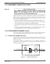
1. Disconnect the sample inlet tubing from the rear panel SAMPLE port (Figure 3-4).
2. Attach the outlet port of a flow meter to the sample inlet port on the rear panel.
Ensure that the inlet to the flow meter is at atmospheric pressure.
3. The sample flow measured with the external flow meter should be 650 cm³/min
10%.
4. Low flows indicate blockage somewhere in the pneumatic pathway. Refer to
troubleshooting Section 12.3 for more information on how to fix this.
11.3.8. HYDROCARBON SCRUBBER (KICKER)
There are two possible types of problems that can occur with the scrubber: pneumatic
leaks and contamination that ruins the inner tube’s ability to absorb hydrocarbons.
11.3.8.1. CHECKING THE SCRUBBER FOR LEAKS
Leaks in the outer tubing of the scrubber can be found using the procedure described in
Section 11.3.6. Use the following method to determ
ine if a leak exists in the inner
tubing of the scrubber.
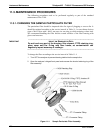
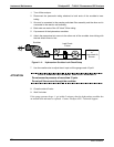
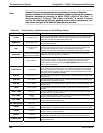
This procedure requires a pressurized source of air (chemical composition is
unimportant) capable of supplying up to 15 psiA and a leak checking fixture such as the
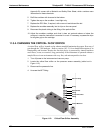
one illustrated in Figure 11-3.
Vacuum/Pressure
Gauge
Manual Shut-Off
Valve
Needle Valve
FROM PUMP or
PRESSURIZED
AIR SOURCE
TO SCRUBBER
Figure 11-3: Simple Leak Check Fixture
06807C DCN6650