


Remote Operation of the Analyzer Teledyne API - T100 UV Fluorescence SO2 Analyzer
176
Connect to Internal
Ground of Monitoring
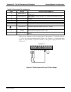
STATUS
1 2 3 4 5 6 7 8 D
+
SYSTEM O
K
HIGH RANGE
CONC VALID
ZERO CAL
SPAN CAL
DIAGNOSTIC MODE
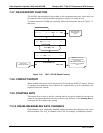
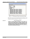
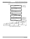
Figure 8-1: Status Output Connector
Table 8-1: Status Output Pin Assignments
CONNECTOR PIN STATUS CONDITION (ON=CONDUCTING)
1
System Ok ON if no faults are present.
2
Conc Valid ON if concentration measurement is valid, OFF when invalid.
3
High Range ON if unit is in high range of any AUTO range mode.
4
Zero Cal ON whenever the instrument is in ZERO calibration mode.
5
Span Cal ON whenever the instrument is in SPAN calibration mode.
6
Diag Mode ON whenever the instrument is in DIAGNOSTIC mode.
7-8
Unused
D
Emitter Bus
The emitters of the transistors on pins 1-8 are bussed together. For most
applications, this pin should be connected to the circuit ground of the
receiving device.
+
Dc Power + 5 VDC source, 30 mA maximum (combined rating with Control Inputs)
Digital Ground The ground from the analyzer’s internal, 5/±15 VDC power supply.
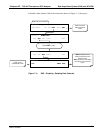
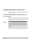
8.1.2. CONTROL INPUTS
Control inputs allow the user to remotely initiate ZERO and SPAN calibration modes
are provided through a 10-pin connector labeled CONTROL IN on the analyzer’s rear
panel. These are opto-isolated, digital inputs that are activated when a 5 VDC signal
from the “U” pin is connected to the respective input pin.
06807C DCN6650