


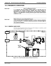

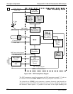
Teledyne API - T100 UV Fluorescence SO2 Analyzer Principles of Operation
301
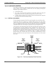
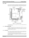
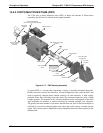
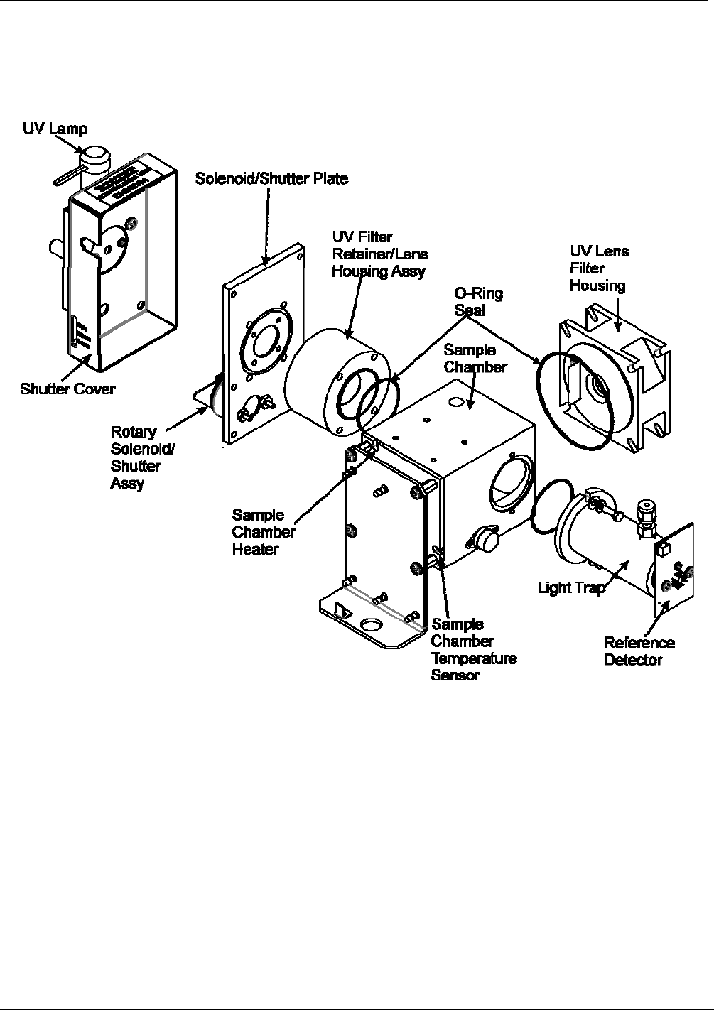
13.5.2.1. SAMPLE CHAMBER
The main electronic components of the sample chamber are the reference detector (refer
to Section 13.1.4); the UV Lamp (refer to Section 13.1.3) and its electronically operated
shutter (refer to Section 13.
1.6); and the sample chamber heating circuit.
Figure 13-16: T100 Sample Chamber
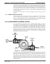
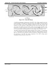
13.5.2.2. SAMPLE CHAMBER HEATING CIRCUIT
In order to reduce temperature effects, the sample chamber is maintained at a constant
50°C, just above the high end of the instrument’s operation temperature range. Two AC
heaters, one embedded into the top of the sample chamber, the other embedded directly
below the reference detector’s light trap, provide the heat source. These heaters operate
off of the instrument’s main AC power and are controlled by the CPU through a power
relay on the relay board. A thermistor, also embedded in the bottom of the sample
chamber, reports the cell’s temperature to the CPU through the thermistor interface
circuitry of the motherboard.
06807C DCN6650