


Teledyne API - T100 UV Fluorescence SO2 Analyzer Principles of Operation
297
13.5. ELECTRONIC OPERATION
Touchscreen
Display
I
2
C
Bus
Iii
(
I
2
C Bus
)
USB
COM1
(RS–232 ONLY)
or USB)
COM 2
(RS–232 or RS–485)
LVDS
transmitter
board
Analog In
Pneumatic
Sensor
Board
Sample
Pressure
Sensor
Sample Flow
Sensor
Analog Outputs
Status Outputs:
1 – 8
Control Inputs:
1 – 6
PC 104
CPU Card
Disk On
Module
Flash Chip
Power-Up
Circuit
I
2
C Bus
Analog
Sensor Inputs
Box
Temp
Thermistor
Interface
SAMPLE
CHAMBER
TEMPERATURE
PMT
Temperature
Sensor
A1
A2
A3
Optional
4-20 mA
A/D
Converter
(V/F)
PC 104
Bus
External
Digital I/O)
COM2
Female
Analog
Outputs
(D/A)
RELAY
BOARD
I
2
C Status
LED
PUMP
A4
RS232
Male
CPU
STATUS
LED
IZS PERM-TUBE
TEMPERATURE
Shutter
control
Sample Cal
Valve
Option
IZS Valve
Option
Reaction Cell
Heater
IZS Option
Permeation
Tube Heater
PMT TEC
PMT
TEC Drive
PCA
Internal
Digital I/O
ELECTRIC TEST CONTRO
L
OPTIC TEST CONTROL
PMT OUTPUT (PMT DET)
HIGH VOLTAGE POWER SUPPLY LEVEL
PMT TEMPERATURE
PMT
PREAMP PCA
UV Reference
Detector
Ethernet
USB COM
port
MOTHERBOARD
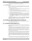
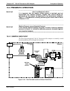
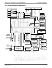
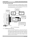
Figure 13-13: T100 Electronic Block Diagram
The core of the analyzer is a microcomputer that controls various internal processes,
interprets data, makes calculations, and reports results using specialized firmware
developed by Teledyne API. It communicates with the user as well as receives data from
and issues commands to a variety of peripheral devices through a separate printed circuit
assembly to which the CPU is mounted: the motherboard.
06807C DCN6650