


APPENDIX A - Version Specific Software Documentation
Rev 1.0.3 (T-Series)/G6 (E-Series)
Teledyne API - Models T100, 100E Series (05036F DCN6650)
A-26 05036 Rev D
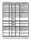
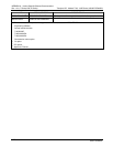
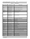
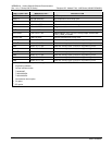
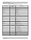
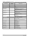
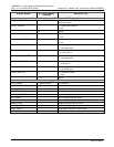
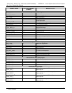
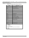
SIGNAL NAME BIT OR CHANNEL
NUMBER
DESCRIPTION
Control outputs, U17, J1008, pins 1–8 = bits 0–7, default I/O address 321 hex
0–7 Spare
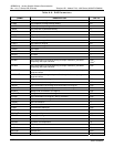
Control outputs, U21, J1008, pins 9–12 = bits 0–3, default I/O address 325 hex
0–3 Spare
Alarm outputs, U21, J1009, pins 1–12 = bits 4–7, default I/O address 325 hex
1 = system OK
0 = any alarm condition or in diagnostics mode
ST_SYSTEM_OK2,
MB_RELAY_36
9
4
Controlled by MODBUS coil register
1 = conc. limit 1 exceeded
0 = conc. OK
ST_CONC_ALARM_1
12
,
MB_RELAY_37
9
5
Controlled by MODBUS coil register
1 = conc. limit 2 exceeded
0 = conc. OK
ST_CONC_ALARM_2
12
,
MB_RELAY_38
9
6
Controlled by MODBUS coil register
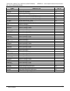
1 = high auto-range in use (mirrors ST_HIGH_RANGE
status output)
0 = low auto-range
ST_HIGH_RANGE2
13
,
MB_RELAY_39
9
7
Controlled by MODBUS coil register
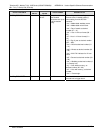
A status outputs, U24, J1017, pins 1–8 = bits 0–7, default I/O address 323 hex
ST_SYSTEM_OK 0 0 = system OK
1 = any alarm condition
ST_CONC_VALID 1 0 = conc. valid
1 = warnings or other conditions that affect validity of
concentration
ST_HIGH_RANGE 2 0 = high auto-range in use
1 = low auto-range
ST_ZERO_CAL 3 0 = in zero calibration
1 = not in zero
ST_SPAN_CAL 4 0 = in span calibration
1 = not in span
ST_DIAG_MODE 5
0 = in diagnostic mode
1 = not in diagnostic mode
ST_LOW_SPAN_CAL
2, 6
6 0 = in low span calibration
1 = not in low span
ST_BKGND_CAL
4
7 0 = in background calibration
1 = not in background calibration
06807C DCN6650