


Troubleshooting & Service Teledyne API - T100 UV Fluorescence SO2 Analyzer
250
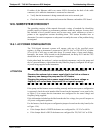
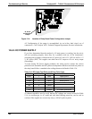
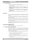
J2: Power
Configuration
Jumper
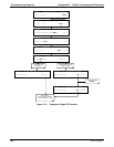
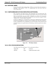
Figure 12-4: Location of Relay Board Power Configuration Jumper
AC Configuration of the pump is accomplished via an in-line, hard wired, set of
connections. Call Teledyne API’s Technical Support Department for more information.
12.6.2. DC POWER SUPPLY
If you have determined that the analyzer’s AC main power is working, but the unit is
still not operating properly, there may be a problem with one of the instrument’s
switching power supplies, which convert AC power to 5 and ±15 V (PS1) as well as +12
V DC power (PS2). The supplies can either have DC output at all or a noisy output
(fluctuating).
To assist tracing DC Power Supply problems, the wiring used to connect the various
printed circuit assemblies and DC powered components and the associated test points on
the relay board follow a standard color-coding scheme as defined in Table 12-4.
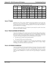
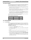
Table 12-4: DC Power Test Point and Wiring Color Code
NAME TEST POINT# COLOR DEFINITION
DGND 1 Black Digital ground
+5V 2 Red
AGND 3 Green Analog ground
+15V 4 Blue
-15V 5 Yellow
+12V 6 Purple
+12R 7 Orange 12 V return (ground) line
A voltmeter should be used to verify that the DC voltages are correct as listed in Table
12-4. An oscilloscope, in AC mode and with band limiting turned on, can be used to
evaluate if the supplies are excessively noisy (>100 mV peak-to-peak).
06807C DCN6650