


Teledyne API - T100 UV Fluorescence SO2 Analyzer Getting Started
37
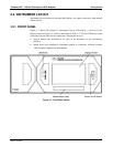
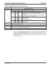
Table 3-2: Display Screen and Touch Control Description
Field Description/Function
LEDs indicating the states of Sample, Calibration and Fault, as follows:
Name Color State Definition
SAMPLE Green
Off
On
Blinking
Unit is not operating in sample mode, DAS is disabled.
Sample Mode active; Front Panel Display being updated; DAS data
being stored.
Unit is operating in sample mode, front panel display being updated,
DAS hold-off mode is ON, DAS disabled
CAL Yellow
Off
On
Blinking
Auto Cal disabled
Auto Cal enabled
Unit is in calibration mode
Status
FAULT Red
Off
Blinking
No warnings exist
Warnings exist
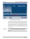
Conc
Displays the actual concentration of the sample gas currently being measured by the analyzer in the
currently selected units of measure
Mode Displays the name of the analyzer’s current operating mode
Param
Displays a variety of informational messages such as warning messages, operational data, test function
values and response messages during interactive tasks.
Control Buttons Displays dynamic, context sensitive labels on each button, which is blank when inactive until applicable.
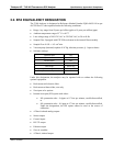
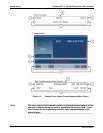
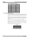
Figure 3-3 shows how the front panel display is ma
pped to the menu charts illustrated in
this manual. The Mode, Param (parameters), and Conc (gas concentration) fields in the
display screen are represented across the top row of each menu chart. The eight touch
control buttons along the bottom of the display screen are represented in the bottom
row of each menu chart.
06807C DCN6650