


Principles of Operation Teledyne API - T100 UV Fluorescence SO2 Analyzer
294
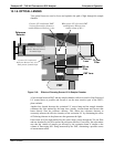
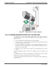
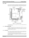
13.4.2. FLOW RATE CONTROL
The T100 uses a special flow control assembly located in the exhaust vacuum manifold
(refer to Figure 13-10) to maintain a constant flow rate of the sample gas through the
instrument. This assem
bly consists of:
A critical flow orifice.
Two o-rings: Located just before and after the critical flow orifice, the o-rings seal
the gap between the walls of assembly housing and the critical flow orifice.
A spring: Applies mechanical force needed to form the seal between the o-rings, the
critical flow orifice and the assembly housing.
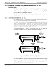
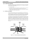
13.4.2.1. CRITICAL FLOW ORIFICE
The most important component of this flow control assembly is the critical flow orifice.
Critical flow orifices are a simple way to regulate stable gas flow rates. They operate
without moving parts by taking advantage of the laws of fluid dynamics. Restricting the
flow of gas though the orifice creates a pressure differential. This pressure differential
combined with the action of the analyzer’s pump draws the gas through the orifice.
As the pressure on the downstream side of the orifice (the pump side) continues to drop,
the speed that the gas flows though the orifice continues to rise. Once the ratio of
upstream pressure to downstream pressure is greater than 2:1, the velocity of the gas
through the orifice reaches the speed of sound. As long as that ratio stays at least 2:1 the
gas flow rate is unaffected by any fluctuations, surges, or changes in downstream
pressure because such variations only travel at the speed of sound themselves and are
therefore cancelled out by the sonic shockwave at the downstream exit of the critical
flow orifice.
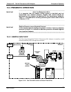
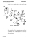
SPRING
O-RINGS
FILTER
CRITICAL
FLOW
ORIFICE
AREA OF
LOW
PRESSURE
A
REA OF
HIGH
PRESSURE
Sonic
Shockwave
Figure 13-11: Flow Control Assembly & Critical Flow Orifice
06807C DCN6650