Teledyne API - T100 UV Fluorescence SO2 Analyzer
xx
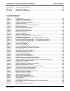
Table 9-4: Example Auto-Cal Sequence.................................................................................................... 200
Table 9-5: Calibration Data Quality Evaluation.......................................................................................... 202
Table 10-1: Activity Matrix for Calibration Equipment & Supplies................................................................ 212
Table 10-2: Activity Matrix for Calibration Procedure................................................................................... 213
Table 10-3: Activity Matrix for Quality Assurance Checks ........................................................................... 215
Table 10-4: Definition of Level 1 and Level 2 Zero and Span Checks......................................................... 216
Table 11-1: T100 Preventive Maintenance Schedule.................................................................................. 225
Table 11-2: Predictive Uses for Test Functions........................................................................................... 227
Table 12-1: Warning Messages - Indicated Failures ................................................................................... 238
Table 12-2: Test Functions - Possible Causes for Out-Of-Range Values ................................................... 240
Table 12-3: Relay Board Status LEDs......................................................................................................... 244
Table 12-4: DC Power Test Point and Wiring Color Code........................................................................... 250
Table 12-5: DC Power Supply Acceptable Levels ....................................................................................... 251
Table 12-6: Relay Board Control Devices.................................................................................................... 252
Table 12-7: Analog Output Test Function - Nominal Values ....................................................................... 253
Table 12-8: Status Outputs Check Pin Out.................................................................................................. 253
Table 12-9: Example of HVPS Power Supply Outputs................................................................................ 257
Table 12-10: UV Lamp Signal Troubleshooting............................................................................................. 269
Table 13-1: Relay Board Status LED’s ........................................................................................................ 308
Table 14-1: Static Generation Voltages for Typical Activities...................................................................... 318
Table 14-2: Sensitivity of Electronic Devices to Damage by ESD............................................................... 319
06807C DCN6650


