Teledyne API - T100 UV Fluorescence SO2 Analyzer
xii
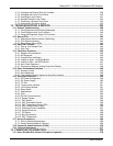
5.2. SETUP – ACAL: Automatic Calibration Option........................................................................................89
5.3. SETUP – DAS: Internal Data Acquisition System....................................................................................90
5.4. SETUP – RNGE: Analog Output Reporting Range Configuration..........................................................90
5.4.1. Available Analog Output Signals ...........................................................................................................90
5.4.2. Physical Range versus Analog Output Reporting Ranges....................................................................91
5.4.3. Reporting Range Modes: Single, Dual, Auto Ranges ...........................................................................92
5.4.4. Range Units ...........................................................................................................................................96
5.4.5. Dilution Ratio (Option)............................................................................................................................98
5.5. SETUP – PASS: Password Protection ......................................................................................................99
5.6. SETUP – CLK: Setting the Internal Time-of-Day Clock........................................................................ 102
5.7. SETUP – COMM: Communications Ports.............................................................................................. 104
5.7.1. ID (Instrument Identification)............................................................................................................... 104
5.7.2. INET (Ethernet)................................................................................................................................... 105
5.7.3. COM1 and COM2 (Mode, Baud Rate and Test Port)......................................................................... 105
5.8. SETUP – VARS: Variables Setup and Definition................................................................................... 106
5.9. SETUP – DIAG: Diagnostics Functions ................................................................................................. 108
5.9.1. Signal I/O ............................................................................................................................................ 110
5.9.2. Analog Output Step Test..................................................................................................................... 111
5.9.3. Analog I/O Configuration..................................................................................................................... 112
5.9.4. Optic Test............................................................................................................................................ 125
5.9.5. Electrical Test ..................................................................................................................................... 126
5.9.6. Lamp Calibration................................................................................................................................. 127
5.9.7. Pressure Calibration ........................................................................................................................... 128
5.9.8. Flow Calibration .................................................................................................................................. 129
5.9.9. Test Channel Output........................................................................................................................... 130
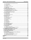
6. COMMUNICATIONS SETUP AND OPERATION ............................................................ 133
6.1. Data Terminal / Communication Equipment (DTE DCE)...................................................................... 133
6.2. Communication Modes, Baud Rate and Port testing........................................................................... 133
6.2.1. Communication Modes ....................................................................................................................... 134
6.2.2. COMM Port Baud Rate....................................................................................................................... 136
6.2.3. COMM Port Testing ............................................................................................................................ 137
6.3. RS-232 ....................................................................................................................................................... 137
6.4. RS-485 (Option)........................................................................................................................................ 138
6.5. Ethernet..................................................................................................................................................... 138
6.5.1. Configuring Ethernet Communication Manually (Static IP Address).................................................. 139
6.5.2. Configuring Ethernet Communication Using Dynamic Host Configuration Protocol (DHCP) ............ 141
6.5.3. USB Port for Remote access.............................................................................................................. 143
6.6. Communications Protocols .................................................................................................................... 145
6.6.1. MODBUS ............................................................................................................................................ 145
6.6.2. HESSEN ............................................................................................................................................. 147
7. DATA ACQUISITION SYSTEM (DAS) AND APICOM..................................................... 153
7.1. DAS Structure........................................................................................................................................... 154
7.1.1. DAS Channels .................................................................................................................................... 154
7.1.2. DAS Parameters................................................................................................................................. 155
7.1.3. DAS Triggering Events ....................................................................................................................... 156
7.2. Default DAS Channels ............................................................................................................................. 156
7.2.1. Viewing DAS Data and Settings ......................................................................................................... 159
7.2.2. Editing DAS Data Channels................................................................................................................ 160
7.2.3. Trigger Events..................................................................................................................................... 162
7.2.4. Editing DAS Parameters..................................................................................................................... 163
7.2.5. Sample Period and Report Period...................................................................................................... 165
7.2.6. Number of Records............................................................................................................................. 166
7.2.7. RS-232 Report Function ..................................................................................................................... 168
7.2.8. Compact Report.................................................................................................................................. 168
7.2.9. Starting Date....................................................................................................................................... 168
7.2.10. Disabling/Enabling Data Channels ................................................................................................... 168
7.2.11. HOLDOFF Feature ........................................................................................................................... 170
06807C DCN6650


